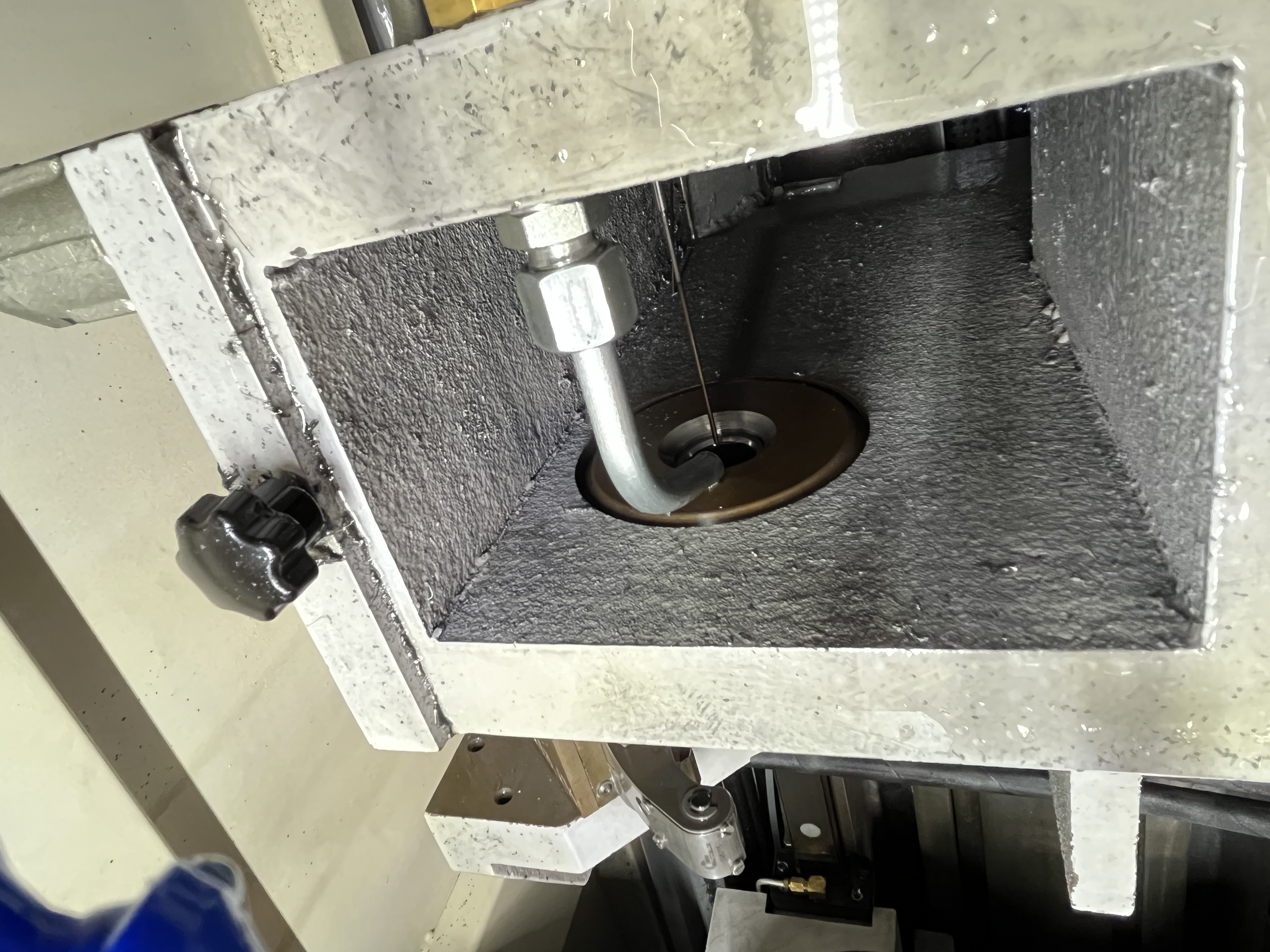
Aerospace hydraulic actuators are similar to industrial cylinders but with tighter tolerances and more exotic materials. I covered industrial hydraulic cylinders in an earlier post; this is about the aerospace version. The jump from industrial to aerospace is not just about hitting tighter numbers – it changes how I plan the entire drilling operation from setup to inspection.
The main differences are material, tolerance, and documentation. The material is typically 15-5PH stainless steel instead of 42CrMo4. The tolerance is +0.005mm instead of +0.02mm. Every part gets tracked by serial number with full inspection records. These factors multiply the setup time and require a more disciplined approach to the drilling process.
I have worked on aerospace actuators for landing gear systems, flight control surfaces, and hydraulic power units. Each application has its own specific requirements, but the drilling challenges are consistent across all of them.
Material Selection and Machinability
For 15-5PH stainless, the machinability is different from the industrial steels I am used to. The material is harder and more abrasive. It work-hardens quickly if the cutting edge gets dull. I have to stay on top of tool condition – a worn drill on 15-5PH produces a rough surface finish that is difficult to correct with honing.
I use the following parameters for 15-5PH stainless in the H900 or H1025 condition:
| Parameter | Value | Notes |
|---|---|---|
| Cutting speed | 50-65 m/min | Lower end for H900, higher for H1025 |
| Feed rate | 0.04-0.07 mm/rev | Reduce to 0.03mm/rev for interrupted cuts |
| Coolant pressure | 1500-2000 psi | Minimum 1000 psi at the cutting edge |
| Coolant type | Sulfur-free oil | Prevents staining on the bore surface |
| Tool coating | TiAlN or AlTiN | Required for tool life |
I have also drilled 17-4PH and 13-8Mo stainless steels for aerospace applications. The 13-8Mo is even tougher than 15-5PH. I reduce the cutting speed by another 10% and accept shorter tool life. The carbide cost is a minor line item compared to the part value, so I change tools aggressively.
The work-hardening behavior of these alloys requires a consistent feed rate. If the feed rate drops below 0.03mm/rev, the drill rubs instead of cutting. The rubbing work-hardens the surface layer, which makes the next cutting pass even harder. I have seen parts where the entry zone was work-hardened from a previous pass and the drill could not re-enter without chipping. The solution was to start with a fresh entry surface.
Tolerance and Surface Finish Requirements
The tolerance of +0.005mm on aerospace actuator bores is five times tighter than the +0.025mm I work to on industrial cylinders. At that level, every variable matters: spindle temperature, coolant temperature, tool runout, and drill bushing wear all affect the final bore size.
I control bore size by managing the coolant temperature. The coolant removes heat from the cutting zone, and if the coolant temperature varies, the bore diameter varies with it. I run the coolant through a chiller that maintains 22-24 degrees C. I have measured bore diameter changes of 0.002-0.003mm for every 5-degree change in coolant temperature. On a +0.005mm tolerance, that is half the allowed range.
The surface finish spec is typically Ra 0.4um or better. I leave 0.2-0.3mm for honing after BTA drilling. The honing pass also corrects any minor diameter variation from the drilling operation. The honing stones I use are 400-600 grit for the rough pass and 800-1000 grit for the finish pass. The finish pass removes 0.01-0.02mm and takes 30-60 seconds.
I have developed the following process flow for aerospace actuator bores:
- BTA drill to within 0.2-0.3mm of final size.
- Rough hone with 400-grit stones to remove 0.15-0.20mm.
- Measure bore diameter and taper with air gage.
- Finish hone with 800-grit stones to remove 0.02-0.05mm.
- Final air gage measurement recorded with serial number.
- Borescope inspection for surface defects.
The BTA drilling before honing needs to be straight. If the BTA bore is more than 0.1mm off-center, the honing tool cannot correct it. I check bore position with a coordinate measuring machine after BTA drilling on the first article. If the position is off, I adjust the drill guide before running the rest of the batch.
Documentation and Traceability
The documentation requirements add time to the job. Every bore measurement gets recorded and filed with the part serial number. I have spent as much time filling out inspection reports as I have spent machining aerospace actuators. The traceability is necessary – if a part fails in service, the manufacturer needs to know exactly how it was made.
The paperwork trail includes:
- Raw material cert with heat number and chemistry.
- Setup approval sheet signed by the inspector.
- First article inspection report with full dimensional data.
- In-process inspection records at 25%, 50%, and 75% of bore length.
- Final inspection report with air gage readings at three depths and two orientations.
- Tool change log recording each drill change and the reason.
I have developed a digital tracking system for these records. Each serial number gets a folder with PDF scans of all inspection data. The system is tied to the machine control, so when I finish a bore, the measurement data auto-populates into the inspection form. This cut my paperwork time by about 40% compared to manual entry.
The auditing side is also important. Aerospace customers audit my facility every 12-18 months. They check calibration records for all gages, training records for the operators, and procedure compliance. I keep a binder with current calibration certs for every air gage, micrometer, and profilometer used on aerospace work.
Inspection and Measurement Strategy
I use multiple measurement methods on aerospace bores because the tolerances are tight enough that any single method can give misleading results. An air gage is fast and repeatable but it measures the gap between the jet and the bore surface, not the actual diameter. A mechanical bore gage gives actual diameter but requires careful technique to avoid skewing the reading.
My standard practice is to air gage every bore for diameter control and then bore gage the first and last article for verification. I also use a profilometer to check surface finish at the bore midpoint. The profilometer trace shows the honing pattern and any torn or smeared metal from the cutting process.
I also check bore straightness with a precision straight bar and feeler gage on the first article. The straightness spec for aerospace actuators is typically 0.05mm per meter. I have found that straightness is harder to hold than diameter. A worn drill bushing or inconsistent coolant flow can produce a curved bore that still meets the diameter spec but fails straightness.
The machine selection matters for aerospace tolerances. I use a dedicated BTA machine with a ground spindle and precision guide bushings for aerospace work. The machine spindle runout is checked before every job and must be under 0.005mm. A standard industrial drilling machine with 0.02mm spindle runout cannot hold the aerospace tolerance stack-up. I learned this the hard way after scrapping a first article on a machine that was good enough for industrial work but not for aerospace.
Key Takeaways
- Aerospace tolerances of +0.005mm require active coolant temperature control to maintain consistent bore size.
- 15-5PH and 13-8Mo stainless steels work-harden easily, so consistent feed rate is critical to avoid rubbing.
- BTA drilling before honing must be within 0.1mm of position or the hone cannot correct it.
- Coolant temperature variation of 5 degrees C changes bore diameter by 0.002-0.003mm.
- The documentation workload equals the machining workload on aerospace jobs.
- A digital inspection tracking system cuts paperwork time by about 40% and reduces errors.
- Honing with 400-grit rough stones followed by 800-1000 grit finish stones produces Ra 0.4um consistently.
- Aerospace audits happen every 12-18 months and require current calibration certs for every gage in use.