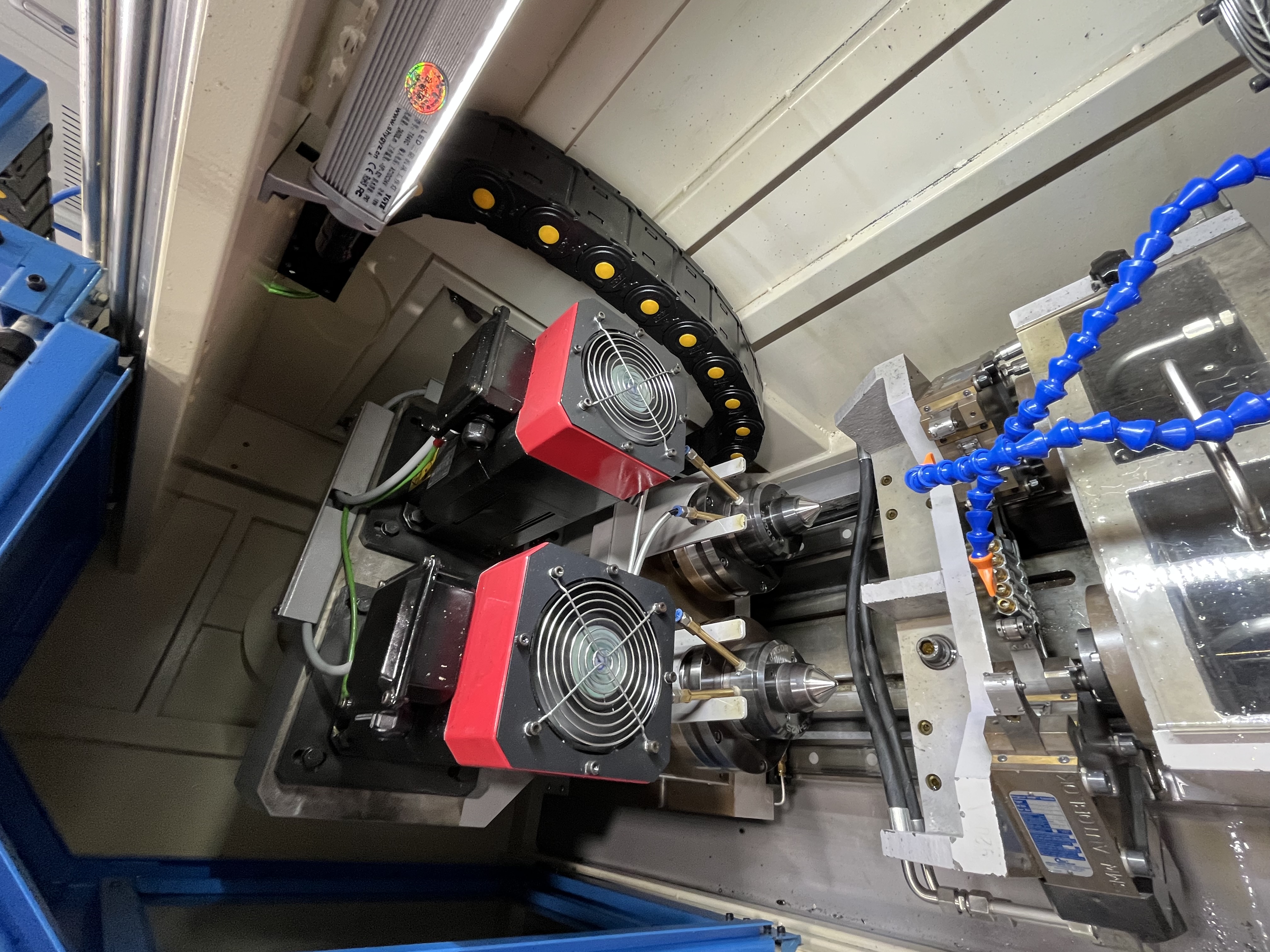
Agricultural sprayer booms are long, lightweight structures that fold out from the sprayer to apply pesticides and fertilizers. They need several types of deep holes — through-holes for fluid passages and cross-holes for nozzle mounting. Over the years I’ve drilled literally thousands of these boom sections, and there are nuances that don’t show up in any textbook.
The boom sections are typically made from aluminum or stainless steel tubing. Aluminum is common for weight reduction — a 30-meter boom set made from 6061-T6 aluminum weighs roughly 40% less than an equivalent 304 stainless build. A typical boom section might have a 20mm through-hole running the full length for the spray fluid, with 6mm cross-holes at regular intervals for the nozzle bodies.
Selecting the Right Material and Geometry
In my experience, the choice between aluminum and stainless steel comes down to the operating environment and budget.
| Property | 6061-T6 Aluminum | 304 Stainless Steel |
|---|---|---|
| Weight per meter (40mm OD x 3mm wall) | 0.97 kg | 2.87 kg |
| Typical wall thickness | 3-5 mm | 2-4 mm |
| Cost index (relative) | 1.0x | 2.3x |
| Corrosion resistance | Moderate | Excellent |
| Fatigue life @ 20MPa cyclic | 10^7 cycles | 10^6 cycles |
I’ve found aluminum is the go-to for most field sprayers, but if the rig handles corrosive chemicals like copper sulfate, stainless is worth the extra cost.
Optimizing Cutting Parameters for Aluminum
For an aluminum boom section, here are the parameters I’ve settled on after extensive testing:
| Parameter | Value | Why |
|---|---|---|
| Cutting speed | 150-200 m/min | Higher speeds prevent built-up edge |
| Feed rate | 0.08-0.12 mm/rev | Keeps chips short and manageable |
| Coolant pressure | 600-800 psi | Flushes chips through the flute |
| Coolant type | 8% oil-in-water emulsion | Best cooling and chip evacuation |
The main challenge is chip control in aluminum. Aluminum produces long stringy chips that can pack up in the bore if the feed is too low. I run the feed at the high end — around 0.12 mm/rev — to keep chips short. If I see a continuous ribbon chip coming out, I know I need to bump the feed up by another 0.01 mm/rev. A well-broken chip looks like a series of 6’s or 9’s.
I also pay close attention to coolant concentration. In one job I had recurring chip packing issues on a 6-meter boom section. The coolant concentration had drifted to 5%. Bumping it back to 8% solved the problem immediately — the added lubricity reduced friction enough that chips flowed freely.
Cross-Hole Positioning and Intersection Accuracy
The cross-holes for nozzle mounting need to intersect the main fluid passage accurately. If a cross-hole misses the passage by more than 1mm, the nozzle does not get fluid. I drill the main passage first, then use a depth-stop to position each cross-hole precisely.
I’ve developed a workflow for positioning:
- Drill the main fluid passage full-length first.
- Load the boom section into a vee-block fixture with end stop.
- Use a drill bushing at each nozzle station to guide the cross-drill.
- Drill cross-holes alternating from left to right to prevent the tube from drifting.
- Inspect every 10th part with a borescope through the main passage.
The most common defect I see is a cross-hole that exits the main passage on the far wall rather than intersecting cleanly. This happens when the cross-drill bushing wears. I replace bushings every 500 cycles — measured, not guessed.
Managing Thin-Wall Deflection
The thin wall of the boom tube is another consideration. The wall thickness is typically 3-5mm. I reduce feed by 20% when drilling cross-holes to prevent the drill from deflecting or grabbing on breakthrough.
Here is how I set up for thin-wall drilling:
| Condition | Feed rate (mm/rev) | Coolant pressure (psi) |
|---|---|---|
| Standard wall (5mm+) | 0.10-0.12 | 700-800 |
| Thin wall (3mm) | 0.08-0.10 | 600-700 |
| Ultra-light (2mm wall) | 0.06-0.08 | 500-600 |
On thin-wall parts, I also use a backup support directly opposite the drill point. Even a 0.1mm deflection will produce an oversize hole and a burr that needs extra cleanup.
Deburring and Final Inspection
Deburring is critical for sprayer booms. A burr inside the fluid passage can break loose and clog a nozzle. I deburr every cross-hole intersection with a carbide burr run through the main passage.
My deburring sequence:
- Carbide manual burr on the OD entry of each cross-hole.
- Flexible shaft rotary burr through the main passage to clean all intersections.
- Compressed air blowout at 90 psi in both directions.
- Borescope inspection of each cross-hole intersection.
- Water flow test on every 50th assembly.
One trick I’ve learned: run a nylon brush through the main passage before the deburr. It dislodges loose chips that otherwise get rolled into the intersection surface by the burr tool.
Key Takeaways
| Area | Key Point |
|---|---|
| Material selection | Aluminum for weight, stainless for chemical resistance |
| Feed rate | Keep it at 0.10-0.12 mm/rev to break chips |
| Cross-hole accuracy | Use drill bushings and replace every 500 cycles |
| Thin-wall tech | Reduce feed 20% and use backup supports |
| Deburring | Borescope every intersection; nylon brush first |
I’ve found that the biggest single improvement to sprayer boom quality came from switching from manual deburring to a consistent documented sequence. Before that, missed burrs were a recurring field complaint. Now they are virtually zero.