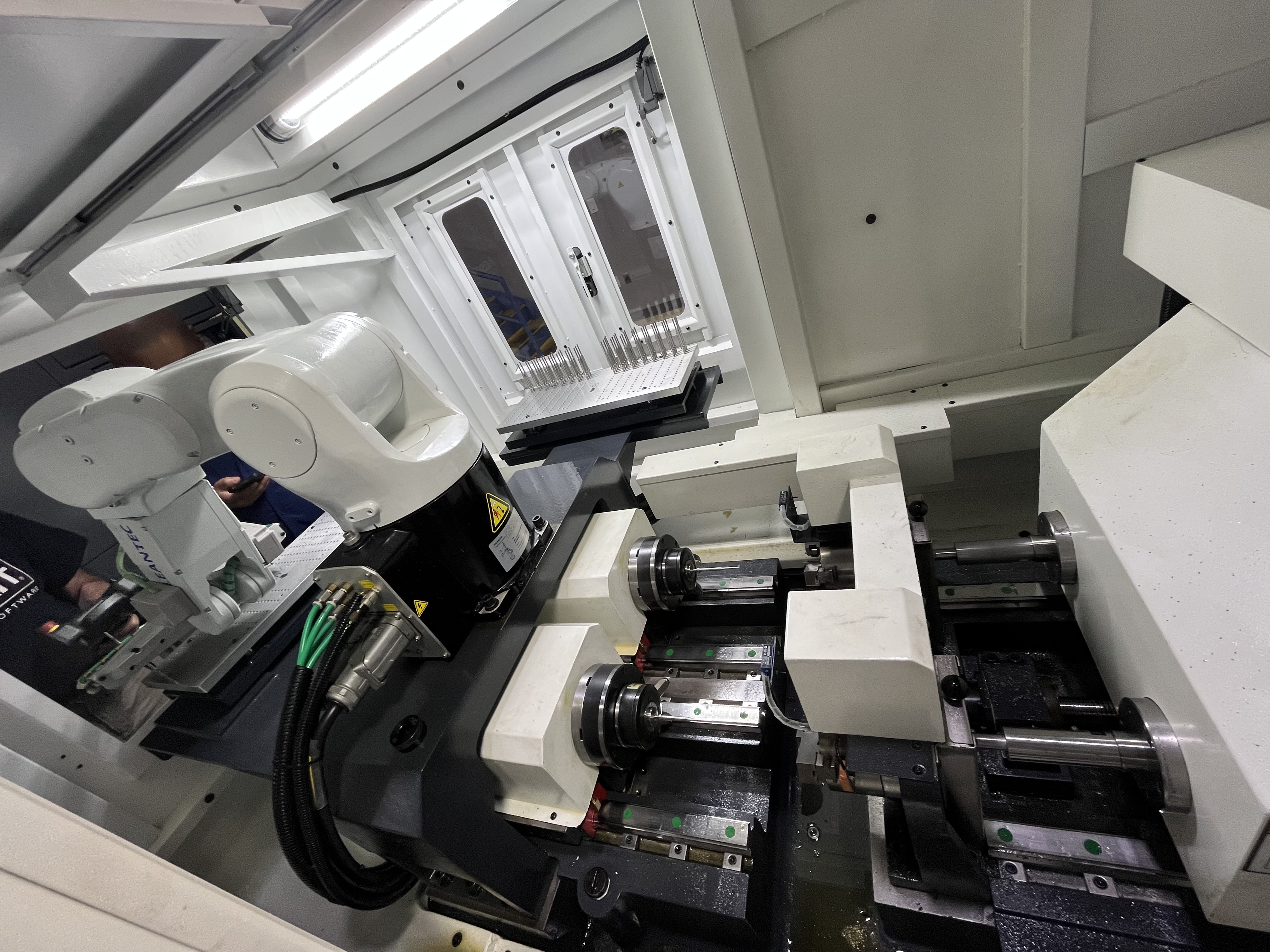
Deep Hole Drilling for EV Battery Cooling Plates: Challenges and Solutions
Over the last few years, I have seen battery cooling plates become one of the fastest-growing applications in our deep hole drilling shop. Every major EV platform now uses liquid-cooled battery packs, and the cooling plate — typically a sandwiched aluminum assembly with internal coolant channels — is at the heart of the thermal management system. As demand has ramped up, so have the calls from manufacturers asking how to adapt deep hole drilling processes to these parts. The short answer is that it works very well, but you have to rethink almost every assumption you carry over from traditional deep hole drilling work.
Typical Cooling Plate Designs
Battery cooling plates are fundamentally different from the round, symmetrical parts most deep hole drillers are used to. They are flat, rectangular assemblies, often made from two stamped or machined aluminum sheets that are bonded together — typically by brazing or friction stir welding — with a network of channels between them. The cooling medium, usually a water-glycol mix, flows through these channels to carry heat away from the battery cells sitting above the plate.
Channel patterns vary by manufacturer, but the most common layouts I encounter are:
- Serial serpentine channels — a single continuous channel that winds back and forth across the plate. Simple to design and machine, but pressure drop can be high.
- Parallel multi-pass channels — several independent channels running the length of the plate, fed by inlet and outlet manifolds. Better thermal uniformity, but requires more drilling.
- Pin-fin or dimpled designs — these use short, blind holes or dimples to create turbulence and increase heat transfer. Drilling requirements here shift toward many closely spaced shallow holes.
- Hybrid configurations — combining any of the above, often with different patterns on the inlet and outlet sides of the plate.
Plate sizes range from small module-level coolers around 200 x 150 mm up to full-pack cold plates exceeding 1200 x 600 mm. Thickness is typically between 6 mm and 20 mm in the finished assembly, with the individual sheets being as thin as 1.5 mm to 3 mm before bonding. The channel cross-sections I drill are usually 4 mm to 12 mm in diameter, with depth-to-diameter ratios that often fall between 10:1 and 40:1.
Materials are almost always aluminum alloys. The table below summarizes what I see most frequently and how they behave under the tool.
| Material | Typical Application | Recommended Feed (mm/rev) | Recommended Speed (m/min) | Coolant Pressure (bar) | Notes |
|---|---|---|---|---|---|
| 3003 aluminum (O/H14) | Brazed cooling plates, good formability | 0.02–0.04 | 80–120 | 40–60 | Soft, gummy — sharp edge prep is critical |
| 6061-T6 | Machined cold plates, higher strength | 0.03–0.05 | 100–150 | 30–50 | Excellent chip formation, very predictable |
| 5052-H32 | Stamped sheets, corrosion resistance | 0.025–0.04 | 90–130 | 35–55 | Moderate gumminess, good surface finish |
| 1100-O | Prototype or deep-drawn plates | 0.015–0.03 | 70–100 | 50–70 | Very soft — risk of built-up edge is high |
| Al-SiC composite | High-performance thermal management | 0.01–0.02 | 50–80 | 60–100 | Abrasive — use PCD or diamond-coated tooling |
I cover gun drilling in aluminum more broadly in my deep dive on gun drilling aluminum, but the table above gives you a starting point specific to cooling plate work.
Drilling Challenges
Cooling plates present a set of challenges that I have not encountered to the same degree in any other deep hole drilling application. Here is what gives my team the most trouble.
Thin-wall drilling. When you are drilling through a 1.5 mm sheet that will later be bonded to a second sheet, there is very little material to support the cutting forces. The drill can push the material away rather than cutting cleanly, leading to exit burrs, distortion, and even tearing between closely spaced holes. I have found that using a back-up support — either a sacrificial aluminum plate clamped behind the workpiece or a custom fixture with drilled-out nests — is essential for maintaining hole quality on thin-gauge material.
Burr control. Burrs are the number one quality complaint I hear from cooling plate customers. A burr left on the coolant channel surface can break loose during operation and circulate through the battery cooling system, potentially clogging pumps or damaging downstream components. Because the plates are often brazed after drilling, any burr at the bond interface can also create a local gap that prevents proper joining, leading to leaks. I address this with a combination of sharp tool geometry (a small or zero-land chamfer on the insert), controlled feed rate during exit, and sometimes a separate deburring pass with a back-spot-facing tool.
Chip evacuation in shallow holes. This sounds counter-intuitive — shallow holes should be easier for chip evacuation, not harder — but in practice, shallow holes in cooling plates are problematic because gun drills rely on the hole depth to establish stable chip flow. With depth-to-diameter ratios under 10:1, the chip has very little distance to break into the characteristic small segments you want, and long, stringy chips can get caught between the drill shank and the hole wall. I mitigate this by increasing coolant pressure at the drill tip (60 bar or higher) and selecting a drill geometry with a chip breaker that triggers at shorter intervals.
Cross-hole intersections. Many cooling plate designs call for intersecting channels — for example, a vertical hole that connects the inlet manifold to a horizontal serpentine channel. Drilling into an existing void changes the cutting forces abruptly and can cause the drill to skive off the intended path. I handle this by reducing the feed rate by 40–50% in the final 2 mm before the expected intersection and by using a drill with a thicker web for added rigidity.
Stack-up tolerances. When you are drilling a plate that will later be bonded to a mating sheet, the positional accuracy of every hole matters. A misaligned hole by even 0.1 mm can cause a channel wall to become too thin, creating a burst risk under coolant pressure. I hold hole positions to within ±0.05 mm relative to the plate datum and verify the first article on a CMM before releasing the batch.
Parameter Recommendations for Aluminum Cooling Plates
Through trial and error across dozens of cooling plate programs, I have developed the following parameter set as my starting point for 6061-T6, which I find the most forgiving aluminum alloy for this application.
- Spindle speed: 8,000–12,000 RPM (adjust toward the lower end for holes above 8 mm diameter to keep surface speed within the optimal 100–150 m/min window).
- Feed rate: 0.03–0.05 mm/rev. I favor the lower end for hole diameters under 6 mm and for thin sheet applications where push-off is a concern.
- Coolant: Water-soluble oil at 8–10% concentration, minimum 50 bar at the drill tip, filtered to 25 microns or better. Cooling plates generate fine aluminum chips that can clog coolant nozzles if the filtration is too coarse.
- Pecking: I generally do not peck with gun drills in aluminum (it interrupts the hydrodynamic chip flow), but for shallow holes under 8 mm depth, a single retraction at mid-depth helps clear any stringy chips that might have formed.
- Entry and exit: Use a drill bushing or a pre-drilled starter hole for entry. For exit, back the feed down to 0.015 mm/rev for the last 1–2 mm of material.
For other alloys, refer back to the material vs. parameter table above. I have found that 3003, in particular, requires a significantly sharper cutting edge and higher coolant pressure than 6061 to avoid built-up edge. If you are transitioning from steel or cast iron work, expect to increase your spindle speed by a factor of 3–4 and your feed by a factor of 2–3 compared to what you are used to.
Quality Requirements
Cooling plate customers hold their suppliers to a level of quality that rivals aerospace work. The two areas that get the most scrutiny are leak testing and cleanliness.
Leak testing. Every cooling plate I have ever shipped has been 100% leak-tested, typically with dry air or helium. The acceptance criteria vary, but a common spec is a maximum leakage rate of 1 x 10⁻⁵ mbar·L/s for helium. This means every through-hole and every channel intersection must be completely free of cracks, porosity, and incomplete penetration. I have had plates fail leak test because of a single burr that prevented proper sealing at a brazed joint. The drilling process must be stable enough that no secondary sealing operations are needed downstream.
Cleanliness. Battery cooling systems cannot tolerate particulate contamination. Chips, burrs, cutting fluid residue, or any foreign material inside the coolant channels can cause blockages or galvanic corrosion over time. My standard process after drilling is:
- High-pressure wash (200+ bar) with an aqueous cleaner directed through every channel.
- Ultrasonic cleaning for parts small enough to fit in our tank.
- Forced hot-air drying until the internal channels are completely moisture-free.
- Cleanliness verification via particle count or microscopic inspection of flushed fluid.
Dimensional requirements. Beyond leak tightness, customers typically specify:
- Hole diameter tolerance: ±0.025 mm
- Hole position tolerance: ±0.05 mm relative to datum
- Surface roughness inside the channel: Ra 1.6 µm or better
- Burr height: 0.05 mm maximum, preferably zero
Here is a quick reference for the most common defects I have encountered and how I address them.
| Defect | Likely Cause | Solution |
|---|---|---|
| Exit burr > 0.1 mm | Excessive feed at exit, dull insert | Reduce feed to 0.015 mm/rev through exit; replace insert more frequently |
| Chip wrapping around drill | Insufficient coolant pressure, low chip breaking | Increase coolant pressure to 60+ bar; switch to chip-breaker geometry |
| Hole oversize (out of tolerance) | Worn guide pads, spindle runout | Inspect guide pads; check spindle concentricity (< 0.005 mm TIR) |
| Surface tear / rough finish | Built-up edge on the insert, low speed | Increase surface speed to 120+ m/min; ensure coolant concentration is adequate |
| Hole position drift | Fixture deflection, worn bushing | Verify clamping force; replace drill bushing every 500 holes |
| Leak at channel intersection | Burr or debris preventing braze flow | Improve deburring process; add compressed-air blow-off before bonding |
| Material push-off / distortion | Thin wall, excessive feed | Reduce feed rate; add back-up support plate |
Production Considerations
Scaling cooling plate drilling from a prototype run of 50 pieces to a production run of 50,000 requires planning that goes beyond the cutting parameters.
Fixturing. I use vacuum fixtures for flat plate work whenever possible. They provide uniform clamping without distorting thin parts and allow quick changeover between plate sizes. For plates with existing channel features (pre-formed or machined), a dedicated nest fixture with locating pins is more reliable. I design fixtures with through-holes aligned to every drill position so that chips and coolant exit cleanly rather than pooling under the part.
Tool life and monitoring. Gun drills in aluminum cooling plates can achieve 500–2,000 holes per edge depending on the alloy, with 6061 at the high end and Al-SiC composites at the low end. I track tool life by hole count and use spindle load monitoring to detect insert wear in real time. A gradual 10–15% increase in spindle load is my signal to change the tool before quality degrades.
Secondary operations. Most cooling plates go through some combination of deburring, cleaning, and leak testing after drilling. I have found it efficient to integrate a deburring robot cell inline with the drilling machine for high-volume work. The robot can back-spot-face every hole in under 30 seconds per plate, which is much faster than manual deburring and far more consistent.
Process validation. Before releasing a new cooling plate design to production, I run a capability study on at least 30 parts, measuring hole diameter, position, and burr height at multiple locations across the plate. I also section a sacrificial plate and inspect the internal channel geometry under a microscope. This upfront investment has saved me from expensive rework more times than I can count.
I have also written separately about deep hole drilling for EV motor shafts, which is another rapidly growing application driven by the same electrification trend. The challenges there are different — concentricity and surface finish in long, slender parts — but the quality mindset is the same.
Key Takeaways
- Battery cooling plates are flat, aluminum assemblies with internal coolant channels that require deep hole drilling to create the channel network. Common alloys include 3003, 5052, and 6061 in thicknesses from 1.5 mm to 3 mm per sheet.
- The three biggest drilling challenges are thin-wall distortion, burr control (especially exit burrs), and chip evacuation in shallow depth-to-diameter ratio holes. Each can be managed with the right process adjustments.
- Starting parameters for 6061-T6 are 8,000–12,000 RPM, 0.03–0.05 mm/rev feed, and minimum 50 bar coolant pressure. Reduce feed by 40–50% at hole exits and at channel intersections.
- Quality requirements are stringent: leak testing (typically helium, 1 x 10⁻⁵ mbar·L/s), cleanliness verification, diameter tolerance of ±0.025 mm, and burr height under 0.05 mm are common specifications.
- Production success depends on proper fixturing (vacuum or nest-style), tool life monitoring via spindle load, and integrated secondary operations for deburring and cleaning.
- The same deep hole drilling principles apply across EV applications — motor shafts and cooling plates are both growing segments worth investing in.