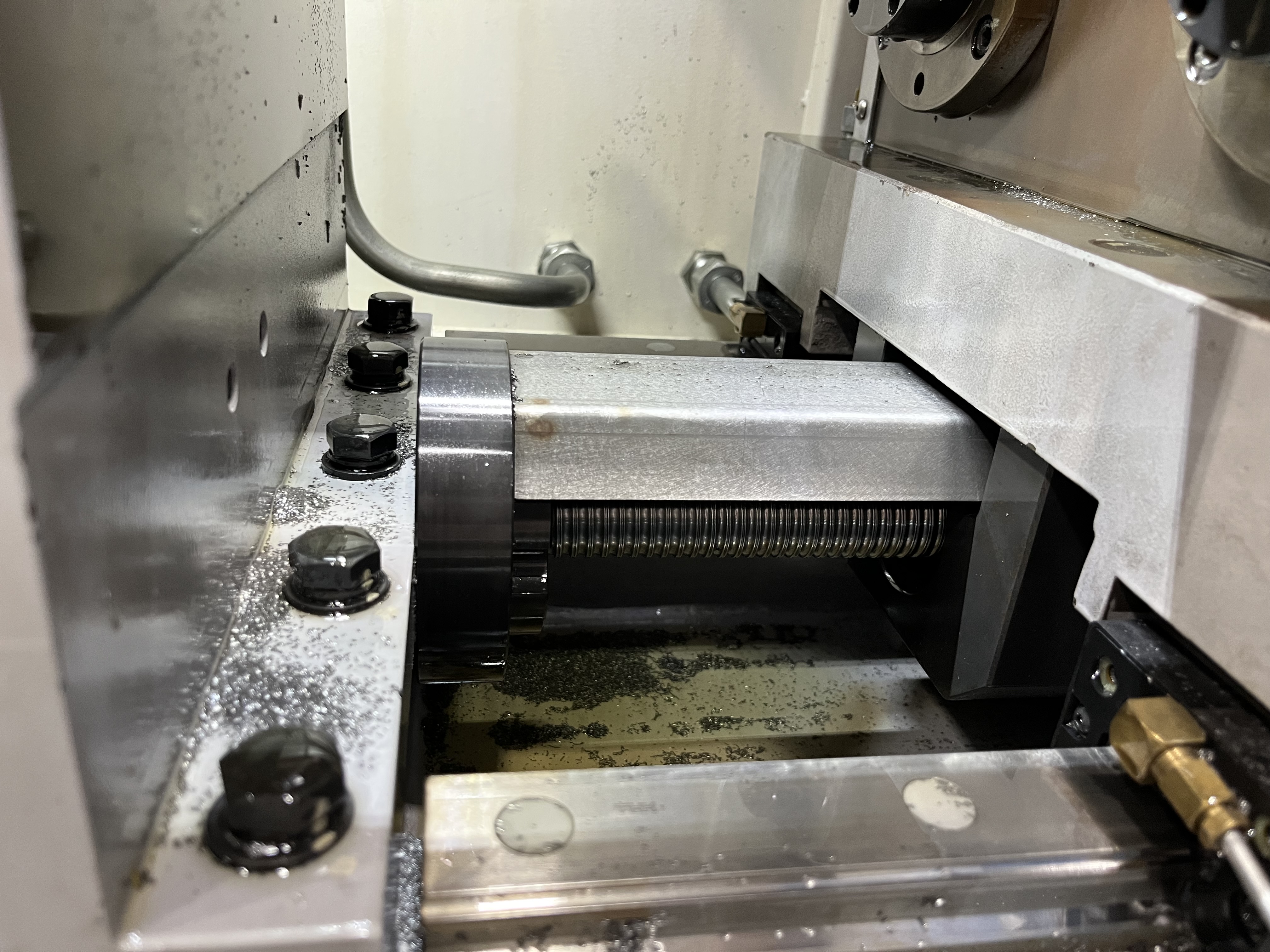
Forklift mast cylinders lift and tilt the forks. These cylinders operate at high pressure and need reliable seal performance. The bore quality directly affects the lifting capacity and service life. In my experience, even a 0.05mm deviation in bore roundness can cut seal life in half.
Bore Geometry and Material Selection
A typical mast cylinder has a 60-120mm bore through 500-1500mm of barrel. The material is usually cold-drawn seamless steel tube or forged steel. The surface finish requirement is Ra 0.8um for good seal life.
I have drilled mast cylinders in the following common sizes:
| Bore Diameter (mm) | Barrel Length (mm) | Wall Thickness (mm) | Typical Material |
|---|---|---|---|
| 60 | 500-800 | 5-8 | ST52.3 seamless |
| 80 | 600-1200 | 6-10 | 25CrMo4 forged |
| 100 | 800-1400 | 8-12 | 4140 steel |
| 120 | 1000-1500 | 10-14 | 4340 steel |
The material choice matters for drilling. Cold-drawn seamless tubes have better internal consistency than welded tubes. I always specify seamless for BTA drilling because weld seams can cause tool deflection and inconsistent surface finish.
BTA Drilling Parameters and Setup
For an 80mm bore in a forklift mast cylinder, this is what I typically run:
| Parameter | Value Range | Notes |
|---|---|---|
| Cutting speed | 60-80 m/min | Lower end for thicker walls |
| Feed rate | 0.08-0.14 mm/rev | Reduced 20% on thin-wall parts |
| Coolant pressure | 300-500 psi | Minimum 300 psi for chip evacuation |
| Coolant flow rate | 150-250 L/min | Must clear chips from cutting zone |
| BTA head insert grade | P25-P35 carbide | Impact-resistant grade preferred |
The main challenge I have encountered is the thin wall relative to the bore. Mast cylinders often have a wall thickness of only 5-10mm to keep the cylinder weight down. A thin wall can deflect under cutting forces, causing the bore to be larger at the center than at the ends. I reduce the feed by 20% on thin-wall mast cylinders to minimize deflection. I also use a steady rest at the center of the barrel for support.
Coolant pressure is critical in BTA drilling of mast cylinders. If the pressure drops below 250 psi, chip evacuation becomes unreliable and the BTA head can overheat. I monitor coolant pressure continuously during the operation and stop the feed if it drops below the threshold.
Honing and Final Sizing
After BTA drilling, I hone the bore to the final diameter and surface finish. The honing stock is typically 0.15-0.25mm. The honing pass corrects any minor taper from the drilling operation.
I have found that a three-stage honing process works best:
- Rough honing at 0.10mm stock removal using CBN honing stones, 60 grit
- Finish honing at 0.05mm stock removal using CBN stones, 150 grit
- Plateau honing at 0.01mm stock removal for final surface finish of Ra 0.8um
The plateau honing step is what I add for cylinders that need extended seal life. It creates a cross-hatch pattern that retains oil and reduces seal wear. I check the surface finish with a profilometer after each step.
Thread Concentricity and Rod End Machining
The rod end of the cylinder often has a threaded section for the piston attachment. I drill and tap this after the main bore is finished. The thread needs to be concentric with the bore within 0.1mm for the piston to seal properly.
My procedure for rod end machining:
- Mount the cylinder on a lathe using the bore as the reference
- Indicate the bore within 0.02mm TIR at both ends
- Face the rod end square to the bore axis
- Bore the thread pilot diameter concentric with the main bore
- Single-point the thread to ensure concentricity
I have found that single-point threading gives better concentricity than thread chasing dies. The difference can be as much as 0.08mm in thread pitch diameter runout.
Quality Checks Before Shipment
Before the cylinder leaves the shop, I run these checks:
| Check | Tolerance | Method |
|---|---|---|
| Bore diameter | H7 fit (0.03mm) | Bore gauge at 3 depths |
| Bore roundness | 0.02mm max | Roundness tester |
| Bore straightness | 0.05mm per meter | Mandrel and indicator |
| Surface finish | Ra 0.8um | Profilometer |
| Thread concentricity | 0.1mm TIR | Dial indicator on thread |
Key Takeaways
The most important lesson I have learned drilling forklift mast cylinders is that the thin-wall deflection problem cannot be fully solved by adjusting speeds and feeds alone. The setup — steady rests, chuck alignment, and bore referencing — matters more than any single parameter adjustment. A well-supported cylinder with moderate feeds consistently outperforms a poorly set up part running aggressive parameters. Get the setup right first, then optimize the drilling parameters.