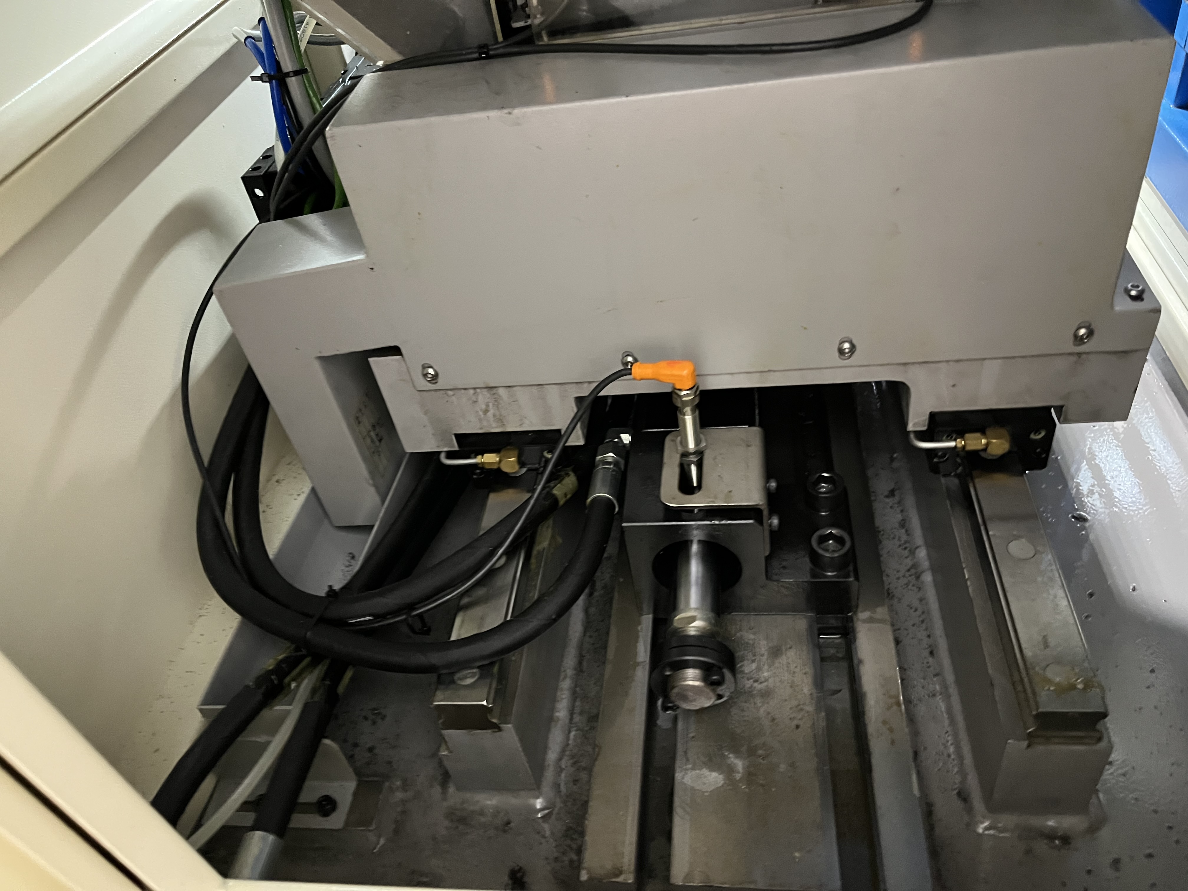
Gears and transmission components are designed to transmit power efficiently, and every hole drilled in them serves a specific purpose. I have drilled thousands of oil holes in gear teeth, lubrication passages through transmission shafts, and weight-reduction bores in gear blanks.
The challenge with transmission components is that they are heat treated after machining. The drilling has to be done before heat treatment (while the material is still machinable), or with special tooling after heat treatment.
Gear Oil Holes
Oil holes in gears provide lubrication to the gear mesh interface. A typical oil hole is 2-8mm in diameter, drilled through the gear tooth root or the gear face at a specific angle to reach the contact zone.
The holes are small and the angles are awkward. I use a gun drilling machine with a tilting workhead to drill oil holes. The workhead tilts to match the required entry angle, usually 15-45 degrees from the gear axis.
Gear Oil Hole Parameters
| Hole Diameter | Gear Material | Cutting Speed | Feed Rate | Coolant Pressure |
|---|---|---|---|---|
| 2-4mm | 8620 (soft) | 60-80 m/min | 0.02-0.04 mm/rev | 1200-1800 psi |
| 4-6mm | 8620 (soft) | 70-90 m/min | 0.03-0.05 mm/rev | 1000-1500 psi |
| 6-8mm | 4340 (soft) | 80-100 m/min | 0.04-0.06 mm/rev | 800-1200 psi |
| 4-6mm | 4320 (soft) | 65-85 m/min | 0.03-0.05 mm/rev | 1000-1500 psi |
The oil holes need to break through into the tooth root without damaging the tooth profile. I drill from the gear face or the gear bore, exiting at the tooth root. The exit point has to be within 0.5mm of the design position to ensure proper lubrication.
Transmission Shaft Lubrication Passages
Transmission shafts have long axial bores that carry oil to the bearings and gears. These are typically 10-30mm in diameter and can be 500-1500mm long. In many designs, the shaft also has cross-drilled holes that intersect the axial bore at right angles.
The cross-drilling is the tricky part. Drilling a hole that intersects an existing bore creates an interrupted cut. When the drill reaches the existing bore, the cutting forces drop suddenly. If the feed does not adjust, the drill can grab and break upon re-entry.
Shaft Boring Parameters
| Parameter | Axial Bore (Gun Drill) | Cross-Drill |
|---|---|---|
| Diameter | 10-30mm | 4-12mm |
| Cutting speed | 70-90 m/min | 50-70 m/min |
| Feed rate | 0.06-0.10 mm/rev | 0.03-0.06 mm/rev |
| Coolant pressure | 600-1000 psi | 1000-1500 psi |
For the cross-drilled holes, I reduce the feed by 40% when the drill approaches the intersection point. I calculate the intersection depth from the drawing and program a feed reduction 2mm before that point. After passing through the intersection, the feed resumes to normal.
Gear Blank Boring
Large gear blanks (500-2000mm diameter) are often through-bored to reduce weight. The bore is typically 100-500mm in diameter. These gear blanks are usually cast or forged steel – either AISI 4140, 4340, or 8620.
Gear blank boring is straightforward BTA drilling. The parameters are similar to what I use for hydraulic cylinder barrels, but with extra attention to the interrupted cut that happens when the drill passes through the web between gear pockets.
Gear Blank Boring Parameters
| Parameter | Value |
|---|---|
| Bore diameter | 100-500mm |
| Cutting speed | 70-100 m/min |
| Feed rate | 0.12-0.20 mm/rev |
| Coolant pressure | 200-400 psi |
| Coolant flow | 300-600 L/min |
Drilling After Heat Treatment
Some transmission components are drilled after carburizing or induction hardening. The surface hardness is typically 58-62 HRC, which requires special tooling.
For post-heat-treatment drilling, I use:
- Polycrystalline cubic boron nitride (PCBN) inserts for diameters over 20mm
- Solid carbide with AlTiN coating for diameters under 20mm
- Speed reduction of 50-60% compared to soft material
- Feed reduction of 20-30%
Post-HT Drilling Parameters
| Parameter | Carburized (60 HRC) | Induction Hardened (55 HRC) |
|---|---|---|
| Cutting speed | 30-50 m/min | 40-60 m/min |
| Feed rate | 0.02-0.04 mm/rev | 0.03-0.05 mm/rev |
| Tool material | PCBN or carbide | Carbide (AlTiN) |
| Coolant pressure | 1500+ psi | 1200-1800 psi |
Key Takeaways
- Gear oil holes need angled entry – a tilting workhead is essential
- Cross-drilled intersection with axial bores requires feed reduction of 40% at the intersection
- Gear blank boring uses standard BTA parameters with attention to interrupted cuts at webs
- Post-heat-treatment drilling needs PCBN or coated carbide with significant speed reduction
- Transmission shafts need straightness tolerances of 0.05mm/m or better
For related topics, see my articles on heat treated components and brake and coupling components.