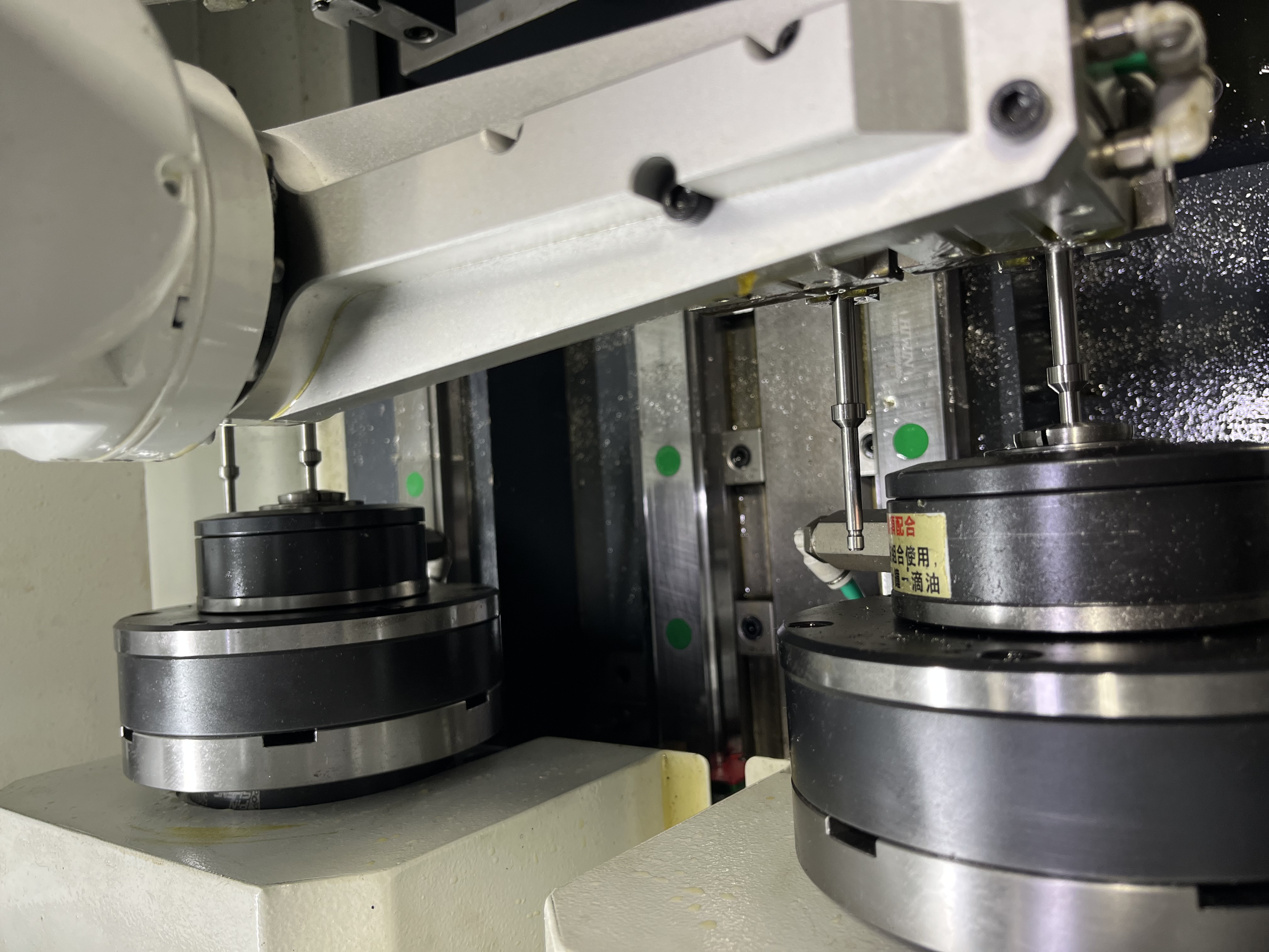
Gearbox shafts are a common deep hole drilling application. The through-hole in a gearbox shaft serves multiple purposes: it delivers lubricating oil to the gear meshes, reduces weight, and provides a passage for control rods in some designs.
I have drilled shafts for industrial gearboxes, automotive transmissions, and heavy equipment drive trains. Each application has similar requirements but different scales. The process requires attention to concentricity, surface finish, and cleanliness of the finished bore.
Types of Shafts and Typical Dimensions
Different gearbox shaft types have different size ranges and drilling requirements. Here is a reference table based on what I see in the shop:
| Shaft Type | Typical OD Range | Through-Hole Diameter | Hole Depth | Common Materials |
|---|---|---|---|---|
| Input shaft (automotive) | 25-50 mm | 10-20 mm | 200-400 mm | 20MnCr5, 17CrNiMo6 |
| Output shaft (automotive) | 30-60 mm | 12-25 mm | 250-500 mm | 20MnCr5, 18CrNiMo7-6 |
| Input shaft (industrial) | 50-120 mm | 20-40 mm | 300-800 mm | 42CrMo4, 34CrNiMo6 |
| Output shaft (industrial) | 60-150 mm | 25-50 mm | 400-1000 mm | 42CrMo4, 34CrNiMo6 |
| Countershaft | 40-100 mm | 15-35 mm | 300-700 mm | 20MnCr5, 18CrNiMo7-6 |
| Idler shaft | 20-50 mm | 8-16 mm | 150-300 mm | 16MnCr5, 20MnCr5 |
The through-hole diameter is typically 30-40 percent of the shaft OD for weight reduction while maintaining sufficient wall thickness for torque transmission. A 50 mm shaft will usually have a 16-20 mm through-hole. Going larger than 40 percent of OD risks the shaft failing in torsion.
Material Grades for Gearbox Shafts
Gearbox shafts are typically made from case-hardening steels or through-hardening alloy steels, depending on the application. Here are the common grades and their machinability:
| Material Grade | Hardness (Before HT) | Case Hardness (After HT) | Machinability Rating | Typical Application |
|---|---|---|---|---|
| 20MnCr5 | 180-220 HB | 58-62 HRC | Good | Automotive gearbox shafts |
| 17CrNiMo6 | 200-240 HB | 58-62 HRC | Good | Heavy-duty gearbox shafts |
| 18CrNiMo7-6 | 200-250 HB | 58-62 HRC | Fair | High-stress gearbox shafts |
| 42CrMo4 | 200-280 HB | 50-55 HRC (QT) | Good | Industrial gearbox shafts |
| 34CrNiMo6 | 220-290 HB | 52-56 HRC (QT) | Fair | Large industrial shafts |
| 16MnCr5 | 170-210 HB | 58-62 HRC | Good | Light-duty idler shafts |
For drilling, the material is in the soft state before heat treatment. The steel is machinable at about 200-250 HB for case-hardening grades and 200-290 HB for through-hardening grades. I always confirm the material condition before setting drilling parameters because hardened material requires completely different speeds and feeds.
Drilling Parameters for Gearbox Shafts
For a typical gearbox shaft in alloy steel before heat treatment, here are the parameters I use:
| Parameter | Value | Notes |
|---|---|---|
| Cutting speed | 80-110 m/min | Use lower end for deeper holes |
| Feed rate | 0.04-0.08 mm/rev | Reduce for deeper holes |
| Coolant pressure | 800-1200 psi (55-83 bar) | Through-tool coolant required |
| Coolant type | Oil-based or high-lubricity emulsion | Surface finish critical |
| Process | Gun drilling | Single lip for most shafts |
| Expected surface finish | Ra 0.8-1.6 micrometers | With optimal parameters |
| Expected concentricity | 0.02-0.04 mm at 400 mm depth | With good setup |
The feed rate depends on the hole depth. A deeper hole needs a lower feed to reduce the risk of drill wandering. I start at 0.06 mm/rev for a 400 mm deep hole and adjust based on the chip formation. If the chips are short and well-formed, I increase the feed. If they are long and stringy or if the drill starts making noise, I reduce it.
For the specific material 20MnCr5, I run at 90-100 m/min cutting speed with a 0.05-0.07 mm/rev feed rate. For 17CrNiMo6, which is tougher, I reduce to 80-90 m/min at 0.04-0.06 mm/rev. These adjustments account for the higher alloy content and work-hardening tendency of the nickel-chromium grades.
Concentricity and Quality Requirements
The through-hole in a gearbox shaft needs to be concentric with the OD to maintain balanced rotation. A hole that is off-center by 0.2 mm in a 50 mm shaft rotating at 3000 RPM creates a measurable imbalance. For high-speed gearbox shafts running above 5000 RPM, the concentricity requirement can be as tight as 0.05 mm total indicated runout.
I check concentricity after drilling by rotating the shaft on V-blocks and measuring the hole position at both ends with a dial indicator. If the hole is within 0.1 mm of center at both ends, the shaft is balanced enough for most applications. For high-speed shafts, I use a CMM to verify the hole position at multiple depths.
| Application | Max Allowable Runout | Inspection Method | Frequency |
|---|---|---|---|
| Automotive transmission shaft | 0.1 mm | V-block and dial indicator | Every 10th part |
| Heavy equipment gearbox shaft | 0.15 mm | V-block and dial indicator | Every 20th part |
| High-speed industrial shaft | 0.05 mm | CMM | Every part |
| Precision aerospace gearbox | 0.03 mm | CMM with full bore map | Every part |
| General purpose shaft | 0.2 mm | Plug gauge check | First part and periodic |
Feed rate has the greatest influence on concentricity in gun drilling. My tests show that reducing feed by 20 percent improves concentricity by about 15 percent. The trade-off is longer cycle time, but for parts with tight concentricity specs, the slower feed is worth it.
Stepped Bores
Some gearbox shafts have stepped bores — a larger diameter at one or both ends that steps down to a smaller diameter through the center. The step corresponds to the stress distribution in the shaft, with larger diameters where higher bending stresses occur.
Drilling a stepped bore requires two passes with different diameter drills. I drill the smaller diameter first, then enlarge the ends with a larger drill or boring tool. The smaller hole acts as a pilot for the larger tool. This sequence maintains concentricity because the small hole guides the larger drill.
The transition between diameters needs a relief radius to avoid stress concentrations. I add a 2-5 mm radius at the step using a form tool or by programming a circular interpolation move.
Oil Hole Drilling
Gearbox shafts often have cross-drilled oil holes that intersect the main through-hole. These are smaller diameter holes — typically 3-8 mm — drilled at an angle to the shaft axis. The intersection must be clean and free of burrs to allow unrestricted oil flow.
The challenge with cross-drilling is the interrupted cut. The drill starts on the shaft OD, passes through solid material, and breaks into the through-hole cavity. The sudden change in cutting forces can break a small drill.
I reduce feed by 50 percent in the last 2 mm before the drill breaks through into the through-hole. This prevents the drill from grabbing when it enters the cavity. A burr or chip in an oil passage can block the oil flow and cause a gearbox failure, so I always deburr the intersections using a flexible shaft tool with a carbide burr. For more shaft drilling insights, see my deep hole drilling for shaft components article.
Key Takeaways
- Gearbox shaft through-holes typically measure 30-40 percent of the shaft OD for optimal strength-to-weight ratio
- Common gearbox shaft materials include 20MnCr5, 17CrNiMo6, and 42CrMo4, all drilled in the soft state before heat treatment
- Drilling parameters for case-hardening steels in the soft state are 80-110 m/min cutting speed with 0.04-0.08 mm/rev feed
- Concentricity of 0.02-0.04 mm is achievable at 400 mm depth with proper setup and a sharp gun drill
- Stepped bores should be drilled with the small diameter first, then the large diameter using the small hole as a pilot
- Feed rate reduction of 50 percent in the last 2 mm before breakthrough prevents drill grabbing during cross-drilling operations
- Surface finish target for gearbox shaft bores is Ra 0.8-1.6 micrometers with oil-based coolant and optimal feed rates
- Every oil passage intersection must be deburred to prevent gearbox failure from blocked oil flow