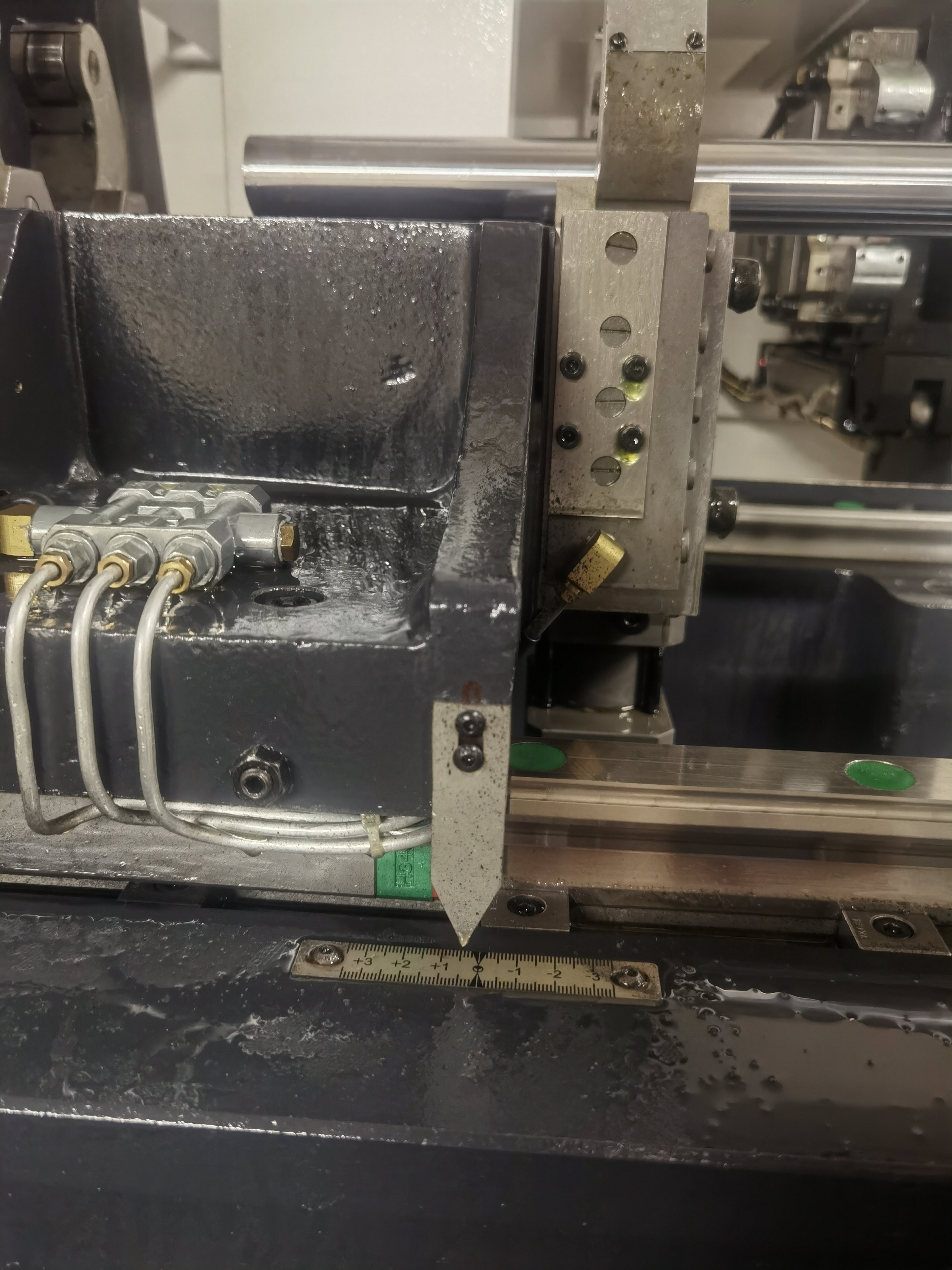
Helical gear shafts are used in industrial gearboxes, automotive transmissions, and heavy equipment drive trains. Many of these shafts need a through-hole for lubrication oil to reach the gear meshes or bearing surfaces. In my experience, the drilling quality directly determines whether the gearbox runs quietly for 10,000 hours or fails from oil starvation after 500.
Common Gear Shaft Materials and Dimensions
The shaft is typically 200-600mm long with a 10-30mm through-hole. The material is usually case-hardening steel like 20MnCr5 or 17CrNiMo6. The drilling is done before heat treatment when the material is soft, around 200-250 HB.
Here are the gear shaft sizes I have drilled most frequently:
| Shaft Length (mm) | Through-Hole (mm) | Shaft OD (mm) | Material | Application |
|---|---|---|---|---|
| 200-300 | 10-12 | 40-60 | 20MnCr5 | Automotive transmission |
| 300-450 | 12-18 | 60-80 | 17CrNiMo6 | Industrial gearbox |
| 450-600 | 18-25 | 80-120 | 18CrNiMo7-6 | Heavy equipment drive |
| 600-800 | 25-30 | 120-160 | 34CrNiMo6 | Wind turbine gearbox |
Drilling before heat treatment is important. The material is 200-250 HB in the soft state, which gives good chip formation and tool life. After case hardening, the surface hardness reaches 58-62 HRC, which would destroy carbide drills. I always schedule the deep hole drilling early in the process flow.
Gun Drilling Parameters for Gear Shafts
For a 15mm through-hole in alloy steel before heat treatment, this is the parameter set I start with:
| Parameter | Value Range | Notes |
|---|---|---|
| Cutting speed | 80-110 m/min | Higher end for softer materials |
| Feed rate | 0.04-0.07 mm/rev | Lower end for deep holes |
| Coolant pressure | 800-1200 psi | Must be stable within 50 psi |
| Coolant type | Oil-based | Sulfurized oil preferred |
| Chip size target | 0.5-2mm | Loaded chips indicate trouble |
I have found that coolant pressure stability matters more than the absolute pressure value for gun drilling gear shafts. A pulsating pump causes the drill to vibrate and produces a wavy bore surface. I use a dampened coolant system with an accumulator to smooth out the pressure.
Concentricity Challenges
The main challenge I have encountered is concentricity. The through-hole needs to be centered in the shaft so the shaft stays balanced at operating speed. I check concentricity by rotating the shaft on V-blocks and measuring the hole position at both ends. The hole should be within 0.15mm of center at each end.
Here is my concentricity troubleshooting guide:
| Runout at Ends (mm) | Cause | Fix |
|---|---|---|
| Less than 0.10 | Acceptable | Proceed to next operation |
| 0.10-0.15 | Marginal | Check drill guide bushing wear |
| 0.15-0.25 | Drill wandering | Reduce feed by 20%, verify starting spot |
| 0.25-0.50 | Misaligned guide bushing | Realign bushing with shaft centerline |
| Over 0.50 | Starting spot drill was off-center | Re-spot drill and re-start hole |
I have learned that the starting spot drill is the single most important factor for concentricity. If the spot is 0.05mm off center, the full-length hole will be 0.15-0.30mm off center by the time it reaches the far end. I spend extra time getting the spot drill position exactly right.
Stepped Bore Design and Drilling Sequence
Another challenge is the stepped bore design. Some gear shafts have a larger diameter at one or both ends that steps down to a smaller diameter through the center. I drill the smaller diameter first through the full length, then enlarge the ends with a larger drill. The smaller hole acts as a pilot for the larger drill.
My stepped bore drilling sequence:
- Center-drill both shaft ends with a spot drill
- Gun drill the full length at the smallest diameter (e.g., 15mm)
- Enlarge the first end to the larger diameter (e.g., 25mm) to the step depth
- Flip the shaft and enlarge the second end to the same larger diameter
- Deburr both step edges where the diameter changes
The step depth tolerance is typically +0.5mm. I use a depth stop on the larger drill to control the step position. Over-drilling the step depth can weaken the shaft at the step transition.
Oil Passage Cross-Holes and Deburring
Oil passage cross-holes are common in gear shafts. These are small-diameter holes drilled at an angle from the shaft surface into the main through-hole. The intersection of the cross-hole and the main hole needs to be deburred to prevent metal particles from circulating in the oil system.
I have developed a deburring procedure for these intersections:
- Use a carbide burr tool with a 90-degree tip to reach the intersection
- Rotate the shaft and check with a borescope that the burr is fully removed
- Flush the hole with high-pressure coolant to push out any loose chips
- Blow compressed air through the main hole to verify unobstructed flow
A single burr left in an oil passage can cause a bearing failure within hours of startup. I treat the deburring step as a quality gate — if the part has not been deburred and verified, it does not move to heat treatment.
Key Takeaways
- Drill gear shaft through-holes before heat treatment while the material is in the soft state
- Concentricity is determined at the spot drilling step — getting the spot right prevents most wandering issues
- Stepped bores must be drilled small-to-large, using the smaller hole as a pilot
- Cross-hole intersections require thorough deburring and borescope verification
- Coolant pressure stability is more important than peak pressure for gun drilling quality