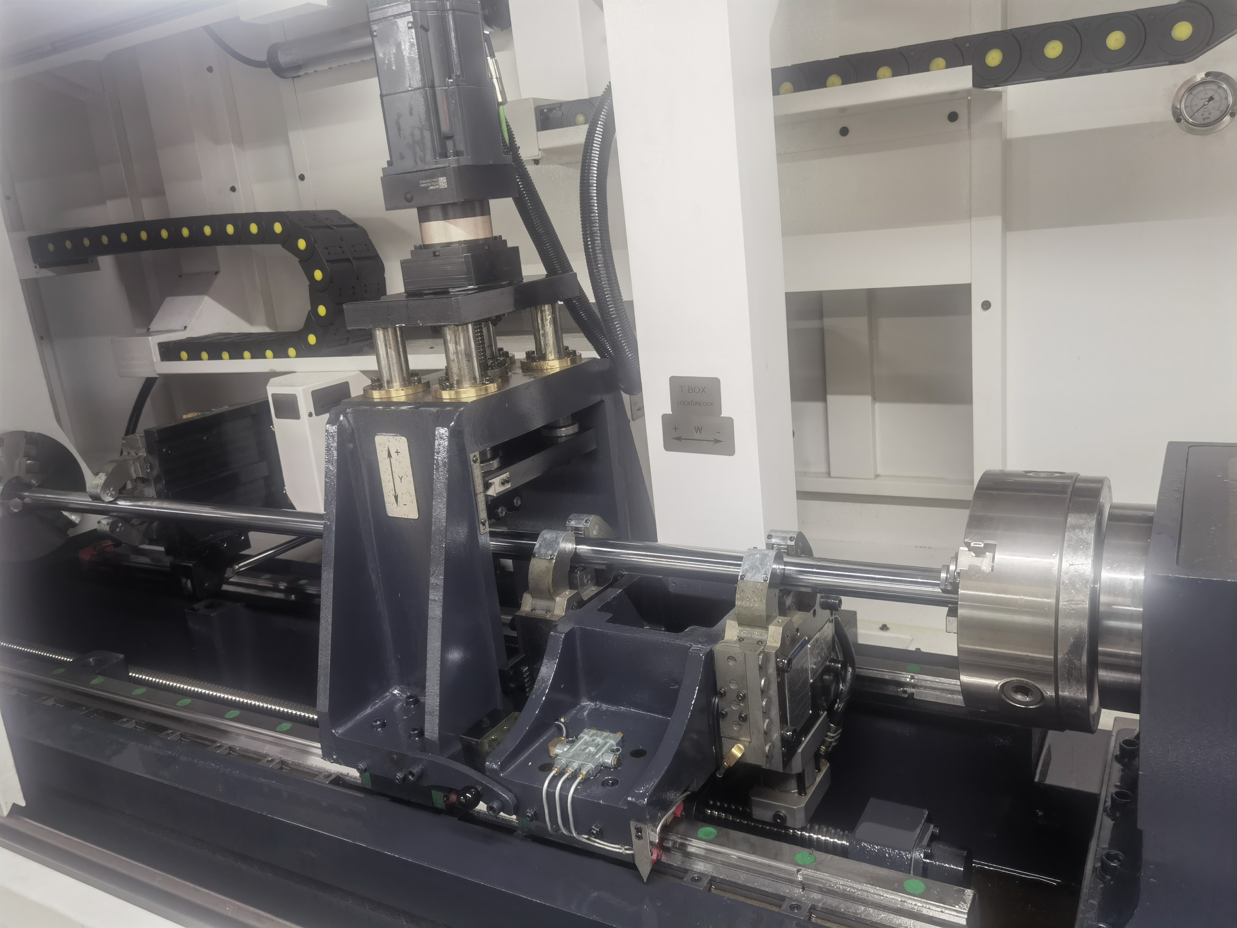
Hot runner manifolds are one of those jobs where the drilling itself is not the hard part. The hard part is making sure the holes meet where they are supposed to meet, and that the intersections are clean enough for plastic to flow through without hanging up.
I have done my share of manifold drilling. If you are new to mold drilling in general, the injection mold components article covers the basics. This one is specifically about manifold channels and the techniques I use for deep hole drilling of hot runner manifolds.
The Layout Is Everything
A typical hot runner manifold starts as a block of steel — usually H13, 4140, or P20 — with a network of channels that need to intersect precisely. A missed intersection by 0.5 mm means the channel does not connect, and the block is scrap. A manifold block can cost $1000-3000 or more, so getting it right the first time matters.
I start by verifying the hole positions against the print before I drill anything. On a manifold with multiple intersections, I lay out every hole center and check the distances between them. If the print says two holes should intersect at 200 mm depth, I need to know exactly how far apart they are at the surface and at what angle they meet.
For angled intersections, I always drill a test block first. A scrap piece of the same material, same thickness, same hole pattern. I have caught angle errors on test blocks that would have scrapped a $2000 manifold block. The test block takes an hour to make but saves thousands in potential scrap.
Manifold Material Comparison
Hot runner manifolds are made from several grades of tool steel and pre-hardened steel, depending on the operating temperature and plastic type. Here is a comparison of the common materials I work with:
| Material | Hardness Range | Max Operating Temp | Machinability | Wear Resistance | Cost Factor |
|---|---|---|---|---|---|
| H13 (pre-hardened) | 38-42 HRC | 600 deg C | Fair | Excellent | High |
| H13 (annealed, then HT) | 44-48 HRC | 600 deg C | Poor (HT state) | Excellent | High |
| 4140 (pre-hardened) | 28-32 HRC | 400 deg C | Good | Good | Moderate |
| P20 (pre-hardened) | 28-34 HRC | 400 deg C | Good | Good | Moderate |
| Stainless 420 | 30-35 HRC | 350 deg C | Fair | Fair | High |
| Aluminum 7075 | 150-175 HB | 200 deg C | Excellent | Poor | Low |
Most hot runner manifolds I drill are H13 in the pre-hardened condition at 38-42 HRC. The material is tough but machinable with carbide gun drills. I run about 25 percent lower cutting speed in H13 compared to 4140 to manage tool wear. For H13 at 40 HRC, I use 50-65 m/min cutting speed with 0.03-0.06 mm/rev feed rate.
Channel Layout Considerations
The channel layout in a hot runner manifold requires planning before any drilling starts. The layout determines how well the manifold distributes melt to each cavity.
| Layout Type | Typical Channel Count | Intersection Points | Complexity | Best For |
|---|---|---|---|---|
| Straight-through (I-shape) | 1-2 main runners | 1-2 | Low | Single cavity or sprue bar |
| T-shape | 2-3 runners | 1 | Low | Two cavities on one side |
| H-shape | 4-5 runners | 2 | Moderate | Four-cavity layout |
| X-shape | 4-6 runners | 1 (center) | Moderate | Multi-cavity balanced fill |
| Multi-branch tree | 6-12 runners | 3-6 | High | Complex multi-cavity molds |
| Stack manifold | 4-8 runners (two levels) | 4-8 | Very high | Stack mold applications |
For H-shape and branch layouts, I check the intersection angles carefully. A 90-degree intersection is straightforward — the channel walls meet cleanly. An acute angle below 45 degrees creates a thin wall section at the intersection that can crack under thermal cycling. I avoid angles below 45 degrees unless the part design absolutely requires it.
The channel diameter is also a layout consideration. Typical manifold channels range from 8 mm to 25 mm diameter. Larger channels improve flow but reduce the wall thickness between channels and the manifold edges. I maintain a minimum wall thickness of 8-10 mm between the channel wall and the manifold edge for H13 steel.
Drilling Parameters for Manifold Materials
Here are the parameters I use for gun drilling manifold channels in different materials:
| Material | Cutting Speed | Feed Rate (10mm drill) | Coolant Pressure | Tool Coating |
|---|---|---|---|---|
| 4140 (28-32 HRC) | 75-90 m/min | 0.05-0.08 mm/rev | 1000-1200 psi (70-83 bar) | TiAlN |
| P20 (28-34 HRC) | 75-90 m/min | 0.05-0.08 mm/rev | 1000-1200 psi | TiAlN |
| H13 (38-42 HRC) | 50-65 m/min | 0.03-0.06 mm/rev | 1200-1500 psi (83-103 bar) | AlTiN |
| Stainless 420 | 40-55 m/min | 0.03-0.05 mm/rev | 1200-1500 psi | AlTiN |
| Aluminum 7075 | 120-180 m/min | 0.08-0.15 mm/rev | 600-800 psi (41-55 bar) | Uncoated |
The most demanding material for manifold drilling is H13 at 42 HRC. The tool wear is significant, and I change drills more frequently than with 4140 or P20. I track tool life by the number of holes drilled and get about 40-60 holes per edge in H13 compared to 80-120 in 4140.
Quality Inspection for Manifold Channels
After drilling, every manifold channel needs inspection to confirm the intersection points are clean and the flow path is unobstructed. Here is the inspection procedure I use:
| Check | Method | Acceptable Result | Action if Failed |
|---|---|---|---|
| Channel intersection alignment | Borescope inspection at each intersection | Hole centers within 0.3 mm at intersection | Determine if flow is affected |
| Surface finish | Surface roughness comparator or profilometer | Ra 1.6 or better | Adjust feed rate for next part |
| Deburring quality | Visual with borescope at intersections | No burrs or sharp edges | Deburr with carbide burr or larger drill |
| Flow test | Pass water or air through each channel sequence | Unrestricted flow through all paths | Clear blockage or rework |
| Leak test | Pressurize channels to operating pressure (1000-3000 psi) | No pressure drop over 5 minutes | Weld or plug leaks |
| Wall thickness | Ultrasonic thickness gauge | Minimum 8 mm wall to edge | Scrap if below minimum |
I run a flow test on every manifold before it leaves the shop. I connect each channel to a water source at 50 psi and verify that water flows freely through the entire path. A manifold that flows well in testing will flow well on the press. A manifold that does not will cause problems that are hard to diagnose once it is installed.
Drilling Order Matters
The sequence matters more than people think. I drill the main through-holes first, then the intersecting branches. The reason is simple: if I drill the branch first and the main hole breaks through at the wrong spot because the drill wandered, I cannot fix it. But if the main hole is already there, I can adjust the branch entry point to compensate.
For a typical Y-shaped or H-shaped manifold pattern:
- Drill the main runner hole — the longest one, usually through the full length
- Drill the secondary runners that intersect it
- Drill the nozzle drop holes last
The nozzle drop holes are usually the shortest and easiest, so by drilling them last I have the most information about the actual channel positions. If a main runner wandered by 0.3 mm, I know the true position before I drill the nozzle drop, and I can adjust accordingly.
Plugging and Sealing
The ends of manifold channels get plugged — usually with a threaded plug or a welded seal. If you are threading the plug hole, make sure the threads do not deform the channel wall. On thin manifold plates 25-30 mm thick, I have seen thread depth calculations that left only 3 mm of wall between the plug and the channel. That is not enough.
For welded seals, the prep matters. I counterbore the channel end to create a clean shoulder for the weld. The counterbore also gives the weld a consistent depth, which makes finishing the surface easier. For more on quality and inspection, see my feed marks troubleshooting guide.
Key Takeaways
- A missed intersection by 0.5 mm scrap a manifold block worth $1000-3000, so verify every hole position before drilling
- Hot runner manifolds are typically H13 at 38-42 HRC and require lower cutting speeds of 50-65 m/min with AlTiN coatings
- Drill the main runner first, then secondary branches, then nozzle drops — this sequence allows compensation for drill wandering
- Maintain minimum 8-10 mm wall thickness between channels and manifold edges in H13 steel
- Flow test every manifold with water at 50 psi before shipping — a good flow test predicts good press performance
- Avoid intersection angles below 45 degrees to prevent thin wall sections that crack under thermal cycling
- Typical manifold channel diameters range from 8-25 mm, with the diameter matched to the part weight and flow requirements
- Deburr every intersection with a carbide burr or slightly larger drill to prevent plastic hang-up points