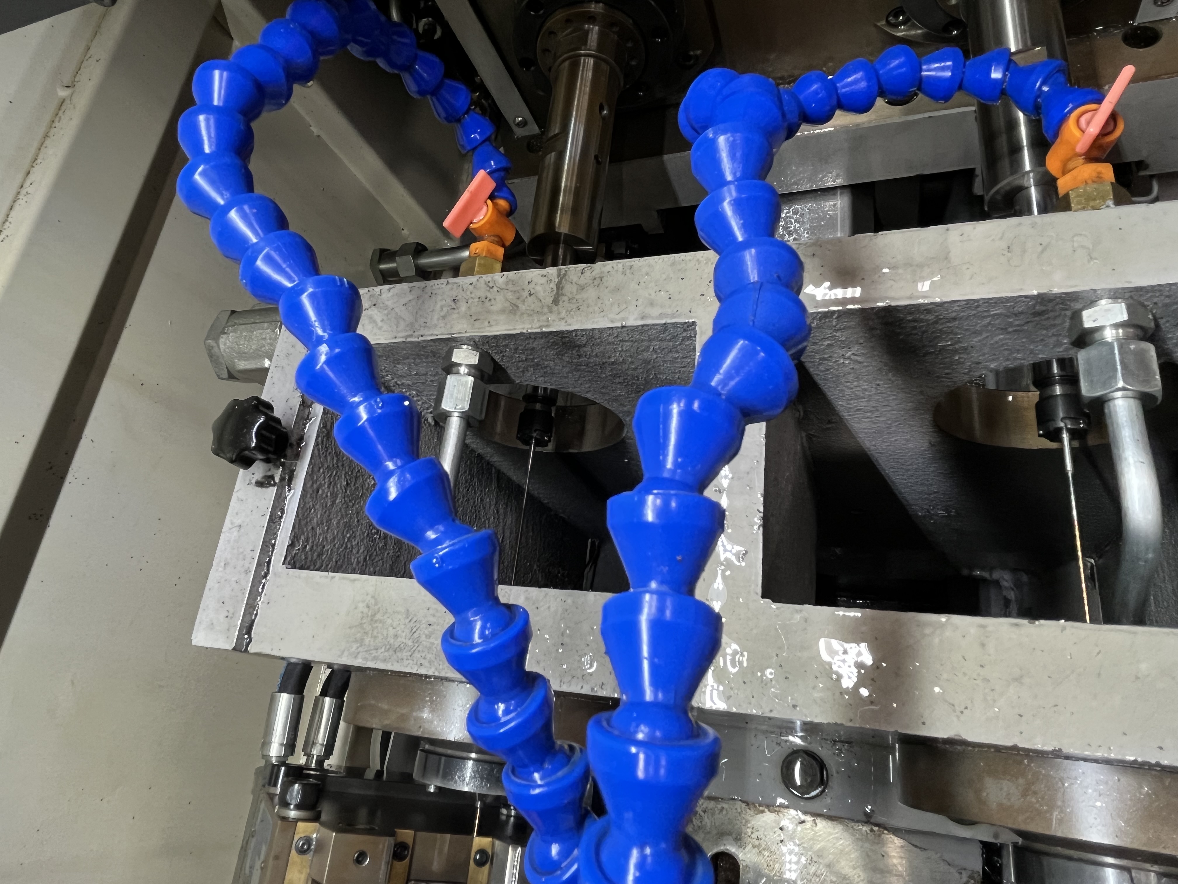
Drilling a long shaft — say 1.5 meters of solid steel with a 10mm hole through the center — looks simple on paper. But it’s one of those jobs where the setup matters more than the cutting parameters. If you’re working on cylinder bores instead of solid shafts, I covered BTA drilling for hydraulic cylinders here. This one is about shafts.
The shaft wants to whip. The drill wants to wander. Coolant has a long way to travel. Here’s how I deal with each.
The Setup Makes or Breaks It
For shaft work, the machine setup is everything. I’ve seen good drills fail because the shaft wasn’t supported properly.
On a shaft longer than about 800mm, I use at least two steady rests. For anything over 1.5 meters, I go with three or four. The idea is to keep the shaft from vibrating at its natural frequency — because once it starts humming, the drill follows and your hole goes bananas.
I space the steady rests evenly along the shaft. If the shaft has a welded flange or a threaded end, I make sure the steady rest isn’t sitting right on that irregularity. That’s a lesson I learned from a job that went straight to scrap because I didn’t check.
Shaft Support Strategy Table
Based on the shaft lengths I have drilled and the results I have tracked, here is the support strategy I use:
| Shaft Length | Number of Steady Rests | Spacing | Support Type | Expected Straightness |
|---|---|---|---|---|
| Under 800 mm | 1 (optional) | At midpoint | Standard roller steady rest | 0.05 mm/300 mm |
| 800 - 1,500 mm | 2 | Evenly spaced at 1/3 and 2/3 | Hydraulic steady rest | 0.08 mm/300 mm |
| 1,500 - 2,500 mm | 3 | Evenly spaced | Hydraulic with damped rollers | 0.10 mm/300 mm |
| Over 2,500 mm | 4 or more | Every 600-800 mm | Hydraulic with rubber-ring supports | 0.15 mm/300 mm |
The last two steady rests (closest to the cutting tip) have the greatest influence on hole straightness. I pay extra attention to the clearance and alignment of those two supports. Research I have reviewed on Euler-Bernoulli beam models for deep hole drilling confirms that adjusting the clearance and direction of the support closest to the cutting head significantly reduces straightness deviation.
Coolant Pressure Gets Tricky at Depth
When you’re drilling a 10mm hole through 1.5 meters of steel, the coolant has to travel that entire distance, clear the chips, and still have enough pressure at the cutting edge to do its job.
I start at around 1200-1500 psi for a 10mm gun drill in medium steel. If the chips are coming out short and broken, I back off until I find the minimum stable pressure. Running higher pressure than needed just wears out seals and heats up the oil faster.
One thing I’ve learned: watch the return pressure, not just the supply gauge. If the return pressure creeps up, chips are starting to pack. That’s your warning to pull out and clear the hole before the drill snaps.
Alignment Is a Two-Person Job
For shafts over a meter, I don’t trust a single alignment check. I check at the headstock, at each steady rest, and at the tailstock. Then I drill a test piece if I can spare one.
The tolerance I aim for is within 0.05mm TIR at the headstock and within 0.1mm at the furthest steady rest. If it’s out past that, the drill will wander — and once it starts wandering, it doesn’t come back.
Parameters I Usually Start With
These are for a medium-carbon steel shaft, gun drilled:
| Parameter | Value |
|---|---|
| Cutting speed | 80-110 m/min |
| Feed rate | 0.02-0.04 mm/rev |
| Coolant pressure | 1000-1500 psi (start high, reduce if stable) |
| Coolant flow | 30-50 L/min for 10mm drill |
The feed rate is the critical one. On shafts, I run a lower feed than I would on a cylinder bore — around 0.025 mm/rev as a starting point. The chips come out as fine dust, which sounds wrong, but it’s what you want. Long chips in a shaft hole will pack up and cause problems fast.
Parameter Adjustments for Long Shafts by Material
The parameters shift depending on the material. Here is what I use for common shaft materials:
| Material | Cutting Speed | Feed Rate | Coolant Pressure | Expected Straightness |
|---|---|---|---|---|
| Medium carbon steel (1045) | 80-110 m/min | 0.025-0.040 mm/rev | 1000-1500 psi | 0.05 mm/300 mm |
| Alloy steel (4140) | 70-90 m/min | 0.020-0.035 mm/rev | 1200-1800 psi | 0.07 mm/300 mm |
| Stainless steel (316) | 60-80 m/min | 0.020-0.030 mm/rev | 1500-2000 psi | 0.08 mm/300 mm |
| Tool steel (H13) | 50-70 m/min | 0.015-0.025 mm/rev | 1400-2000 psi | 0.10 mm/300 mm |
For Inconel 718 shafts, I have seen significant straightness improvements using an EDM pre-drilled guide hole before gun drilling. Research shows this reduces straightness deviation by nearly 50% — from 0.37 mm to 0.19 mm at 350 mm depth — and drops thrust force from 800 N to 250 N.
The Real Test
You know your setup is right when the first few millimeters cut cleanly. If the drill chatters or squeals at entry, stop and check alignment again. It doesn’t get better with depth.
I’ve pulled drills out of shafts at 200mm because the entry was off by 0.1mm, fixed the alignment, and had the next attempt go perfectly. The extra 15 minutes of setup time saved a 2-hour rework.
For more on managing vibration in long shaft deep hole drilling, see my guide on vibration control for thin wall cylinders.
Key Takeaways
- Use at least two steady rests for shafts over 800 mm — the last two supports closest to the cut matter most
- Check alignment at the headstock, each steady rest, and the tailstock — one check is not enough
- Run coolant pressure at 1000-1500 psi for long shafts and watch return pressure for chip packing signs
- Start with a lower feed rate (0.025 mm/rev) to produce fine chips that evacuate easily
- For Inconel shafts, consider EDM pre-drilling the guide hole to improve straightness by nearly 50%
- If the drill chatters at entry, stop and recheck — it will not correct itself with depth
- Parameter adjustments by material make a measurable difference in straightness outcomes