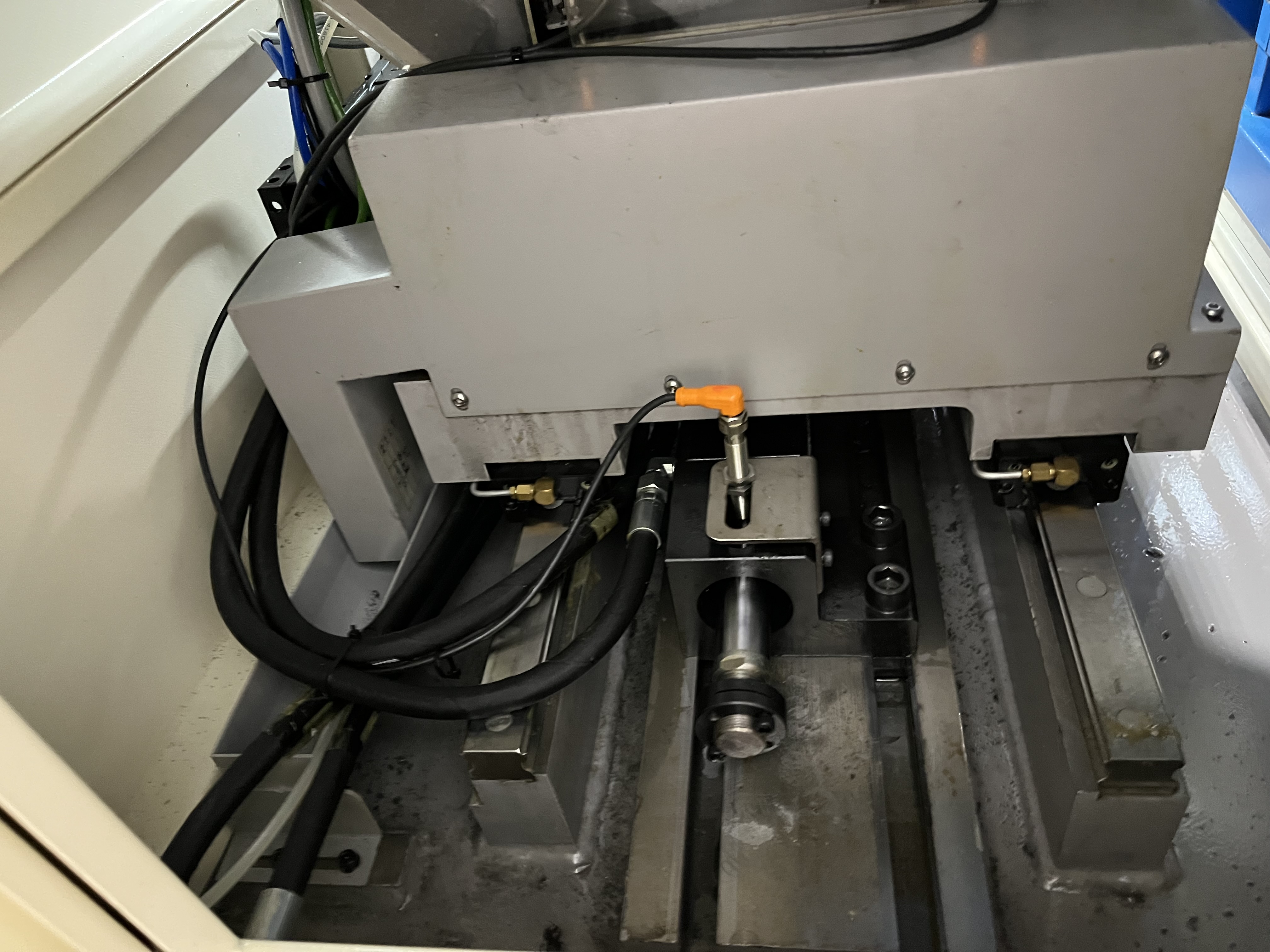
Marine propulsion drive shafts connect the engine or gearbox to the propeller. Many of these shafts need a through-hole running the full length for lubricating oil to reach the stern tube bearing, or for weight reduction on larger vessels. In my experience, the length of marine shafts makes them the most challenging deep-hole drilling application I deal with. A 10-meter shaft with a 50mm bore has a length-to-diameter ratio of 200:1, which pushes the limits of what BTA drilling can achieve.
Shaft Dimensions and Material Selection
A typical shaft might be 6-12 meters long with a 30-80mm through-hole. The material is usually high-strength steel like 34CrNiMo6 or a marine-grade stainless steel. The main challenge is the length — a 10-meter shaft needs careful setup with steady rests every 1.5 meters.
I have worked on marine shafts across a range of vessel types. Here are typical specifications:
| Vessel Type | Shaft Length | Bore Diameter | Material | Bore Purpose |
|---|---|---|---|---|
| Coastal cargo ship | 6-8 m | 30-50 mm | 34CrNiMo6 | Stern tube lubrication |
| Bulk carrier | 8-10 m | 40-60 mm | 34CrNiMo6 | Lubrication + weight reduction |
| Tanker | 10-12 m | 50-80 mm | 34CrNiMo6 | Weight reduction (fuel economy) |
| Naval vessel | 6-10 m | 40-70 mm | Marine-grade stainless | Lubrication + corrosion resistance |
| Yacht | 4-6 m | 30-50 mm | Duplex stainless | Lubrication |
For marine-grade stainless shafts, I reduce cutting speed by 20% compared to 34CrNiMo6 and increase coolant pressure to ensure chip evacuation. Duplex stainless is particularly challenging because of its high strength and tendency to work-harden. I use a lower feed rate (0.08-0.12 mm/rev) with duplex grades to avoid work hardening at the bore surface.
Drilling Parameters and Process Selection
For a 50mm through-hole in high-strength steel, my standard parameters are:
| Parameter | BTA Drilling | Gun Drilling (for smaller bores) |
|---|---|---|
| Cutting speed | 60-80 m/min | 50-70 m/min |
| Feed rate | 0.10-0.18 mm/rev | 0.05-0.08 mm/rev |
| Coolant pressure | 300-500 psi | 800-1200 psi |
| Coolant flow | 300-500 L/min | 100-150 L/min |
| Max L/D ratio | 200:1 | 150:1 |
BTA drilling is the standard method at these diameters. The shaft rotates while the tool advances. The rotation keeps the hole concentric and improves surface finish. I use a two-insert BTA head for marine shafts because the cutting forces are balanced and the head is less likely to drift in long bores.
The feed rate is adjusted based on the chip form I observe at the machine. Ideally, the chips come out as small, broken segments about 5-10mm long. If the chips are stringy or long, I increase the feed rate or adjust the chip breaker geometry. Long chips are dangerous in deep-hole drilling because they can wrap around the drill tube and jam the tool.
Steady Rest Setup and Straightness Control
The straightness requirement is typically 0.5mm per meter. This is achievable with proper steady rest support. I check alignment at every steady rest position before starting the bore. If the shaft sags by more than 0.2mm at any support point, I adjust the steady rest.
My steady rest positioning for a 10-meter shaft:
- Position 1: 1.0m from headstock
- Position 2: 2.5m
- Position 3: 4.0m
- Position 4: 5.5m
- Position 5: 7.0m
- Position 6: 8.5m
The shaft sag calculation for a 10-meter, 300mm diameter shaft (approximately 5.5 tons) shows that without steady rests, the midpoint sag would be 0.8-1.2mm. With steady rests at the positions above, the sag at any point is below 0.1mm.
Shaft rotation speed is 30-60 RPM for marine shafts. The rotation keeps the cutting forces balanced and prevents the tool from riding on one side of the bore. I have found that rotation speeds below 30 RPM increase the risk of bore drift because the cutting forces are not balanced around the circumference.
Chip Evacuation in Long Bores
One issue I have dealt with on long marine shafts is chip evacuation. At 8 meters depth, the chips have a long way to travel. I use a peck cycle with a partial retract every 2 meters to clear chips. The coolant flow needs to be high enough to keep chips moving — I run at least 400 L/min.
The relationship between bore depth and chip evacuation difficulty:
| Bore Depth | Evacuation Time | Coolant Flow Required | Peck Frequency |
|---|---|---|---|
| 0-2 m | Immediate | 300 L/min | None |
| 2-4 m | 1-2 seconds | 350 L/min | Every 2m |
| 4-6 m | 3-5 seconds | 400 L/min | Every 2m |
| 6-8 m | 5-8 seconds | 450 L/min | Every 2m |
| 8-10 m | 8-12 seconds | 500 L/min | Every 1.5m |
I have found that above 8 meters depth, pecking every 1.5 meters instead of every 2 meters reduces the risk of chip packing significantly. The peck cycle retracts the tool by 100-200mm to break up any chip accumulation, then advances again.
Finish Boring and Final Surface Quality
After BTA drilling, I finish-bore to the final diameter. The boring pass removes about 0.5mm and corrects any minor straightness variation from the BTA pass. The surface finish target is Ra 1.6um, which is achievable with a sharp boring head.
The finish boring tool uses a single carbide insert with a wiper geometry. The wiper flat on the insert creates a smooth surface finish at feed rates up to 0.15 mm/rev. I have measured the finish boring pass improving straightness by 0.1-0.2mm per meter in most cases.
Drive shaft bores get inspected with a borescope after drilling. I check for chips, burrs, or tool marks that could contaminate the lubrication system. The borescope inspection covers the full bore length and is recorded as a video file for the quality record.
Key Takeaways
- BTA drilling at 60-80 m/min with 400+ L/min coolant flow handles marine shaft L/D ratios up to 200:1
- Steady rest spacing at 1.0-1.5 meter intervals with sub-0.2mm sag control is essential for straightness
- Peck cycles every 1.5-2m prevent chip packing in bores over 6 meters deep
- Finish boring with a wiper insert removes 0.5mm stock and improves straightness by 0.1-0.2mm per meter
- Duplex stainless marine shafts require 20% lower speed and lower feed rates (0.08-0.12 mm/rev) to manage work hardening