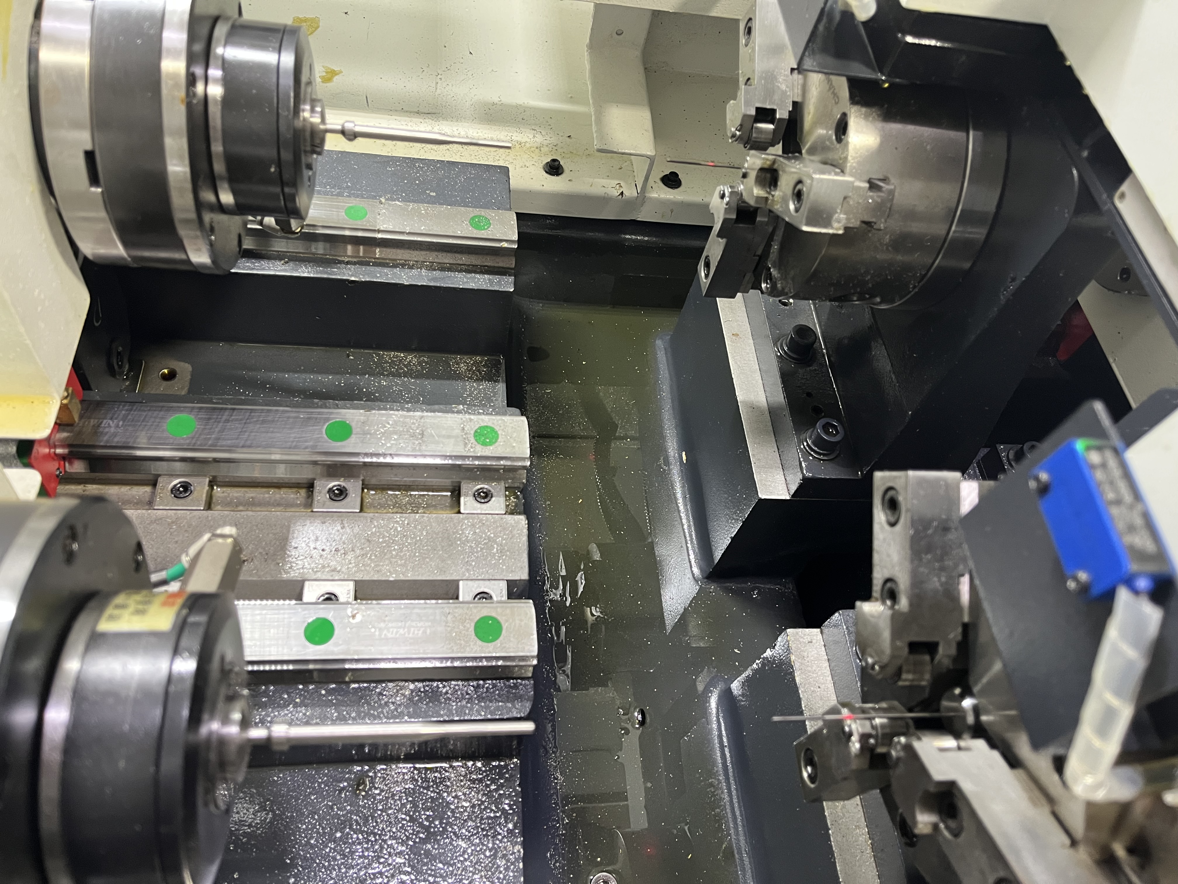
Bone screws are one of the most demanding deep hole drilling applications I have worked on. They look simple — a threaded shaft with a hole through the middle — but that center hole is the reason I treat every bone screw job with extra care. The diameter range is 1 mm to 4 mm, the lengths go up to 150 mm, and the materials are surgical-grade alloys that do not cut easily.
I have covered medical implant drilling at a broader level in another article. This one focuses specifically on bone screws and trauma implants — the designs, the challenges at these diameters, and the parameters that work.
Typical Bone Screw Designs
Most bone screws I encounter fall into two categories: cannulated screws and cortical/cancellous screws.
Cannulated screws have a full-length through-hole — typically 1.0 mm to 2.5 mm in diameter — that allows the screw to be placed over a guide wire during surgery. The guide wire is inserted into the bone first, and the screw slides over it. This means the hole must be straight, burr-free, and concentric to the screw OD. If the hole is off-center by even 0.05 mm, the screw will not track properly over the guide wire.
Cortical and cancellous screws are solid or have a partial drill point, but many trauma implants in this category still have a through-hole for wire fixation or suture attachment. The drilling requirements are the same — straight, clean, burr-free holes through the full length.
The screw sizes I see most often:
| Screw Type | OD Range | Typical Cannulation ID | Length Range | Material |
|---|---|---|---|---|
| Small cannulated (hand/foot) | 2.0-3.0 mm | 1.0-1.5 mm | 10-40 mm | Ti-6Al-4V ELI |
| Standard cannulated (extremity) | 3.5-5.0 mm | 1.5-2.0 mm | 30-80 mm | Ti-6Al-4V ELI |
| Large cannulated (hip/femoral neck) | 6.0-8.5 mm | 2.0-3.5 mm | 70-150 mm | Ti-6Al-4V ELI or 316LVM |
| Trauma nail locking screws | 3.5-5.0 mm | 1.5-2.5 mm | 20-60 mm | 316LVM |
The two materials dominate: Ti-6Al-4V ELI (Extra Low Interstitial) for its biocompatibility and high fatigue strength, and 316LVM (Low Vacuum Melt) stainless steel for its corrosion resistance and lower cost. ELI grade titanium has reduced oxygen and iron content compared to standard Ti-6Al-4V, which improves fracture toughness. It also makes the material slightly more difficult to drill — the reduced interstitial content changes chip formation behavior.
Drilling Challenges at Bone Screw Diameters
At diameters between 1 mm and 4 mm, every problem is amplified. Here are the issues I deal with regularly.
L/D ratios. A 2 mm cannulation through a 120 mm femoral neck screw gives an L/D ratio of 60:1. That is deep hole drilling by any definition, and it is at the low end of what a 2 mm gun drill can handle. The tool is unsupported along most of its length, and any misalignment at the entry is magnified at depth.
Burr control. This is the most critical requirement unique to bone screws. A burr at the hole exit can dislodge during surgery and cause complications. There is zero tolerance for burrs on medical implants. I have had entire lots rejected because a single part showed a burr at the through-hole exit. Achieving burr-free holes at 1.5 mm diameter requires sharp tooling, proper feed at breakthrough, and often a secondary deburring operation.
Tool fragility. A 1.5 mm gun drill has a carbide cross-section that is less than 1 mm thick at the cutting end. The coolant hole is roughly 0.4 mm. The drill cannot tolerate chatter, misalignment, or aggressive feeds. One interruption in coolant flow and the edge is gone in seconds.
Chip evacuation. At these diameters, the chip flute is tiny. Chip packing is the primary cause of tool breakage in bone screw work. I run higher coolant pressure than the equivalent job in larger diameters specifically to keep chips moving.
Parameter Recommendations
The parameters depend on material, diameter, and the specific screw design. Here are the ranges I start from when quoting a new bone screw job.
| Screw Cannulation (mm) | Cutting Speed (m/min) | RPM | Feed (mm/rev) | Coolant Pressure (psi) | Penetration Rate (mm/min) |
|---|---|---|---|---|---|
| 1.0 - 1.5 | 20-30 | 4200-6400 | 0.004-0.008 | 2500-3000 | 17-51 |
| 1.5 - 2.0 | 25-35 | 4000-5600 | 0.006-0.012 | 2000-2500 | 24-67 |
| 2.0 - 2.5 | 30-40 | 3800-5100 | 0.008-0.015 | 1800-2200 | 30-77 |
| 2.5 - 3.5 | 30-45 | 2700-4100 | 0.010-0.018 | 1500-2000 | 27-74 |
For Ti-6Al-4V ELI, I stay at the lower end of the cutting speed range. The ELI grade is tougher than standard Ti-6Al-4V, and the tool life hit is noticeable — about 20% fewer holes per grind based on my production data. For 316LVM, I run at the higher end of the speed range but keep feeds conservative to avoid work hardening.
I covered titanium deep hole drilling parameters in detail elsewhere. For bone screw work specifically, the feed rates are lower than what would work in larger-diameter titanium drilling. The limiting factor is not tool wear — it is drill deflection. At 2 mm diameter with a 100 mm overhang, even 0.015 mm/rev can cause enough deflection to push the hole off-center.
Common Defects in Medical Screw Drilling
I track these defects on every bone screw job. When one of them shows up, I know exactly what to adjust.
| Defect | Root Cause | Correction |
|---|---|---|
| Exit burr | Feed too high at breakthrough; dull tool | Reduce feed by 30-50% in last 3 mm; regrind tool |
| Hole oversize at depth | Drill deflection from high feed or worn bushing | Reduce feed; replace guide bushing |
| Surface finish > Ra 0.8 | Worn cutting edge; inadequate coolant pressure | Regrind tool; verify coolant flow at tool tip |
| Chip packing / tool breakage | Coolant pressure drop; feed too low for chip breaking | Check pump pressure; increase feed by 0.002 mm/rev |
| Hole non-concentric to OD | Misaligned guide bushing; workpiece not centered | Re-align bushing to within 0.01 mm TIR; check chuck concentricity |
| Work-hardened spot mid-hole | Feed interruption; tool dwell | Never stop feed mid-hole; ramp feed on restart |
| Edge chipping on tool | Spindle runout exceeds 0.005 mm; carbide grade too brittle | Check spindle TIR; switch to higher cobalt grade (8-10%) |
Quality and Regulatory Requirements
Bone screws are Class II medical devices in most regulatory frameworks. That classification determines how much documentation and traceability is required.
ISO 13485 is the quality standard I see at every bone screw manufacturer I work with. In practice, it means:
Material traceability. Every blank must be traceable to its heat number. Ti-6Al-4V ELI requires a material certificate from the mill that includes chemical composition and mechanical properties. I log the heat number against each production batch and keep the certificate on file. If a material defect is found, I need to identify every part from that heat within hours.
Process validation. Before the first production run of a new screw design, the drilling process must be validated. I run a sample batch — typically 30 parts — measure every critical dimension, and calculate process capability (Cpk). The customer requires Cpk of 1.33 or higher on hole diameter and concentricity. If the process is not capable, I cannot change parameters and hope — I have to re-validate.
Change management. Once a process is validated, any parameter change — even 0.001 mm/rev in feed — requires formal approval. I have had to document why I increased coolant pressure by 200 psi. The justification gets reviewed by quality engineering and regulatory affairs before it is approved.
Equipment calibration. All gauges used for inspection must have current calibration certificates traceable to NIST or equivalent. Air gauges, pin gauges, micrometers, and surface profilometers all require recalibration on a schedule. I tag each gauge with the calibration due date and pull it from service if the date passes.
Inspection Methods
Every bone screw that leaves the drilling cell gets inspected. There is no sampling — it is 100% inspection on the critical features.
Through-hole diameter. I use air gauging for this. An air plug is inserted into the cannulation from each end, and the airflow through the clearance between the plug and the hole wall is converted to a diameter reading. Air gauging is fast — about 3 seconds per measurement — and accurate to ±0.002 mm. I check both ends of the hole because the diameter can shift along the length, especially at L/D ratios above 40:1.
Concentricity. The relationship between the cannulation centerline and the screw OD is measured on an optical comparator or a coordinate measuring machine. For cannulated screws over 80 mm long, I also check straightness by running a pin gauge through the full length. If the pin binds, the hole is not straight enough.
Surface finish. The bore surface finish is measured with a stylus profilometer. I target Ra 0.4-0.8 microns on the cannulation. Anything rougher than Ra 0.8 increases the risk of crevice corrosion, and anything smoother than Ra 0.4 is unnecessary for the application.
Burr inspection. Every part is visually inspected under 10x-20x magnification at both the entry and exit of the cannulation. For small diameters under 2 mm, I use a borescope to check the internal edges. I also run a cotton swab through the cannulation — if it snags, there is a burr.
Wall thickness. Ultrasonic gauges measure the wall thickness at multiple points around the circumference. Minimum wall thickness is a design requirement that cannot be compromised. A wall that is too thin creates a stress riser that could fail under load.
Key Takeaways
- Bone screw cannulation diameters of 1-4 mm at L/D ratios up to 60:1 place these holes firmly in micro-deep-hole drilling territory — tool fragility and coolant delivery are the primary constraints.
- Burr control is the most critical quality requirement for bone screws. Zero burrs are tolerated, and I reduce feed by 30-50% in the last 3 mm before breakthrough to prevent exit burrs.
- Ti-6Al-4V ELI requires cutting speeds of 20-35 m/min and feeds of 0.004-0.015 mm/rev depending on cannulation diameter — lower than standard Ti-6Al-4V parameters due to the ELI grade’s toughness.
- Coolant pressure must reach 2000-3000 psi at diameters under 2 mm to clear chips and prevent tool breakage from chip packing.
- ISO 13485 requires 100% inspection of bone screw cannulations, full material traceability to heat number, and validated processes with Cpk of 1.33 or higher.
- Feed interruptions mid-hole cause work hardening in both titanium and 316LVM — once the drill starts, keep it moving until the peck is complete.