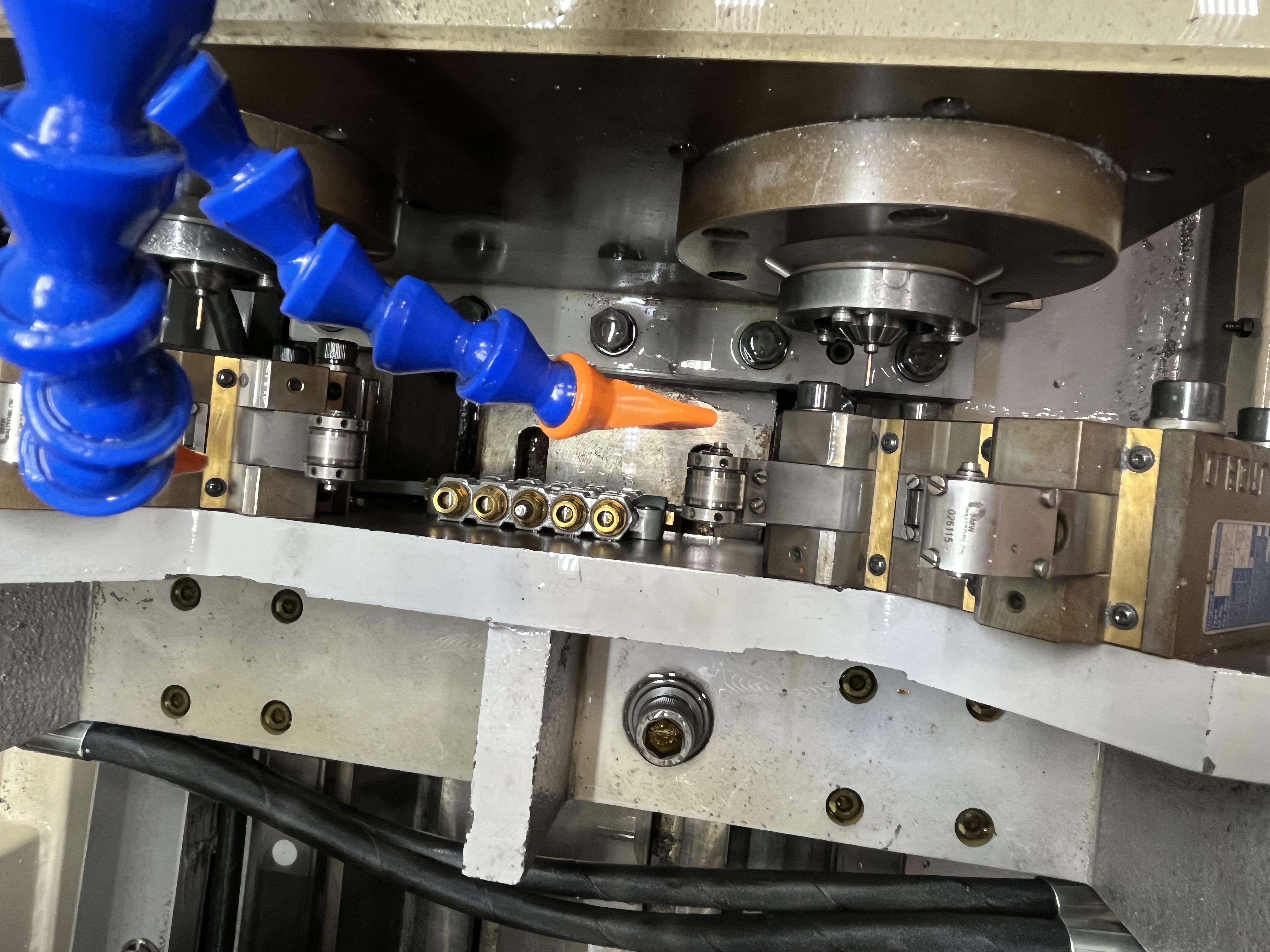
Injection molding machine platens are large steel blocks that hold the mold halves. The moving platen slides on the tie bars through precision-drilled holes. The platens also need drilled cooling channels for temperature control. In my experience, the tie bar hole accuracy determines whether the injection molding machine produces consistent parts over millions of cycles.
Platen Sizes and Material Specifications
A platen for a large injection molding machine can be 1-3 meters wide and 30-60cm thick. The tie bar holes are 80-200mm diameter through the full platen thickness. The position tolerance between the four tie bar holes is typically within 0.1mm.
Here are the platen sizes and tie bar hole configurations I have drilled:
| Machine Size (ton) | Platen Width (mm) | Platen Thickness (mm) | Tie Bar Hole Dia (mm) | Hole Spacing (mm) | Material |
|---|---|---|---|---|---|
| 1000 | 1200 x 1200 | 300 | 80 | 800 x 800 | EN8 or A36 |
| 2000 | 1600 x 1600 | 400 | 120 | 1100 x 1100 | 42CrMo4 |
| 3000 | 2000 x 2000 | 500 | 160 | 1400 x 1400 | 42CrMo4 |
| 4000 | 2400 x 2400 | 600 | 200 | 1700 x 1700 | 42CrMo4 |
The platen material is usually a medium-carbon steel plate. For larger platens over 3000 tons, I recommend 42CrMo4 because it has better dimensional stability after machining. EN8 and A36 are adequate for smaller machines but can distort more during the tie bar hole drilling.
Drilling Parameters for Tie Bar Holes
For boring tie bar holes in a steel platen, these are the parameters I start with:
| Parameter | BTA Drilling | Line Boring |
|---|---|---|
| Cutting speed | 60-80 m/min | 50-70 m/min |
| Feed rate | 0.08-0.14 mm/rev | 0.06-0.10 mm/rev |
| Coolant pressure | 300-500 psi | Not required (dry) |
| Depth of cut per pass | Full diameter | 1-3mm per pass |
| Surface finish (Ra) | 1.6-2.5 um | 0.8-1.6 um |
I choose between BTA drilling and line boring based on the platen thickness:
- Under 400mm thick: BTA drilling is faster — one pass per hole
- Over 400mm thick: Line boring gives better straightness for deep holes
- Over 600mm thick: Line boring with intermediate support bushings
The main challenge I have encountered is maintaining position accuracy. The four tie bar holes must be exactly parallel and at the correct spacing. If the holes are off by more than 0.1mm, the tie bars bind as the platen moves.
Hole Sequence Strategy
I drill the tie bar holes in sequence using the machine CNC positioning. I check the position of the first hole with a CMM before drilling the remaining three. If the first hole is correct, the others will be consistent.
My preferred drilling sequence for a four-hole platen:
- Drill the upper-left tie bar hole first (reference hole)
- CMM-check hole position, diameter, and perpendicularity
- If the first hole passes inspection, drill the upper-right hole
- Drill the lower-left hole
- Drill the lower-right hole last
- Run a final CMM check on all four holes for position and parallelism
I have found that drilling the holes diagonally rather than in order around the platen reduces distortion. The diagonal sequence spreads the thermal load more evenly through the platen. If I drill them in clockwise order, the platen heats up progressively and the last hole ends up slightly out of position.
Cooling Channel Drilling
The cooling channels are smaller holes drilled in a pattern through the platen. I drill these using gun drilling with the platen mounted on the machine table. The channels must be positioned for even cooling across the mold mounting surface.
Cooling channel specifications I typically work to:
| Channel Diameter (mm) | Centers (mm) | Distance from Surface (mm) | Drilling Method |
|---|---|---|---|
| 10-12 | 60-80 | 25-35 | Gun drilling |
| 12-16 | 80-100 | 35-45 | Gun drilling |
| 16-20 | 100-120 | 45-55 | Gun drilling |
The cooling channels are interconnected using cross-drilled holes at the platen edges. The intersections must be deburred to prevent flow restrictions. I use a flexible shaft deburring tool to reach into the cross-hole intersections.
I have learned that cooling channel positioning is as important as the tie bar hole accuracy for the final machine performance. Uneven cooling causes the platen to distort thermally, which affects mold alignment. I map the cooling channel positions against the mold mounting pattern to ensure consistent temperature across the mold mounting surface.
Surface Finish and Deburring
After drilling, I deburr every hole and check the surface finish. The tie bar holes need Ra 1.6um for smooth sliding. The cooling channels need to be clean and free of chips.
My deburring process:
- Tie bar hole edges are chamfered with a 2mm x 45-degree edge break
- Cooling channel openings are deburred with a carbide burr
- Internal hole intersections are checked with a borescope
- All holes are flushed with high-pressure coolant after deburring
- Final blow-out with compressed air removes all residue
I have found that a borescope inspection of internal intersections catches burrs that would otherwise only be discovered during machine assembly. A single burr at a cooling channel intersection can restrict coolant flow and cause a hot spot on the platen surface.
Key Takeaways
- Diagonal drilling sequence reduces thermal distortion compared to sequential clockwise drilling
- BTA drilling is best for platens under 400mm thick, line boring for thicker platens
- CMM-check the first tie bar hole before committing to the remaining three
- Cooling channel positioning directly affects platen temperature uniformity
- Borescope inspection of internal cross-hole intersections catches hidden burrs that cause flow restrictions in service