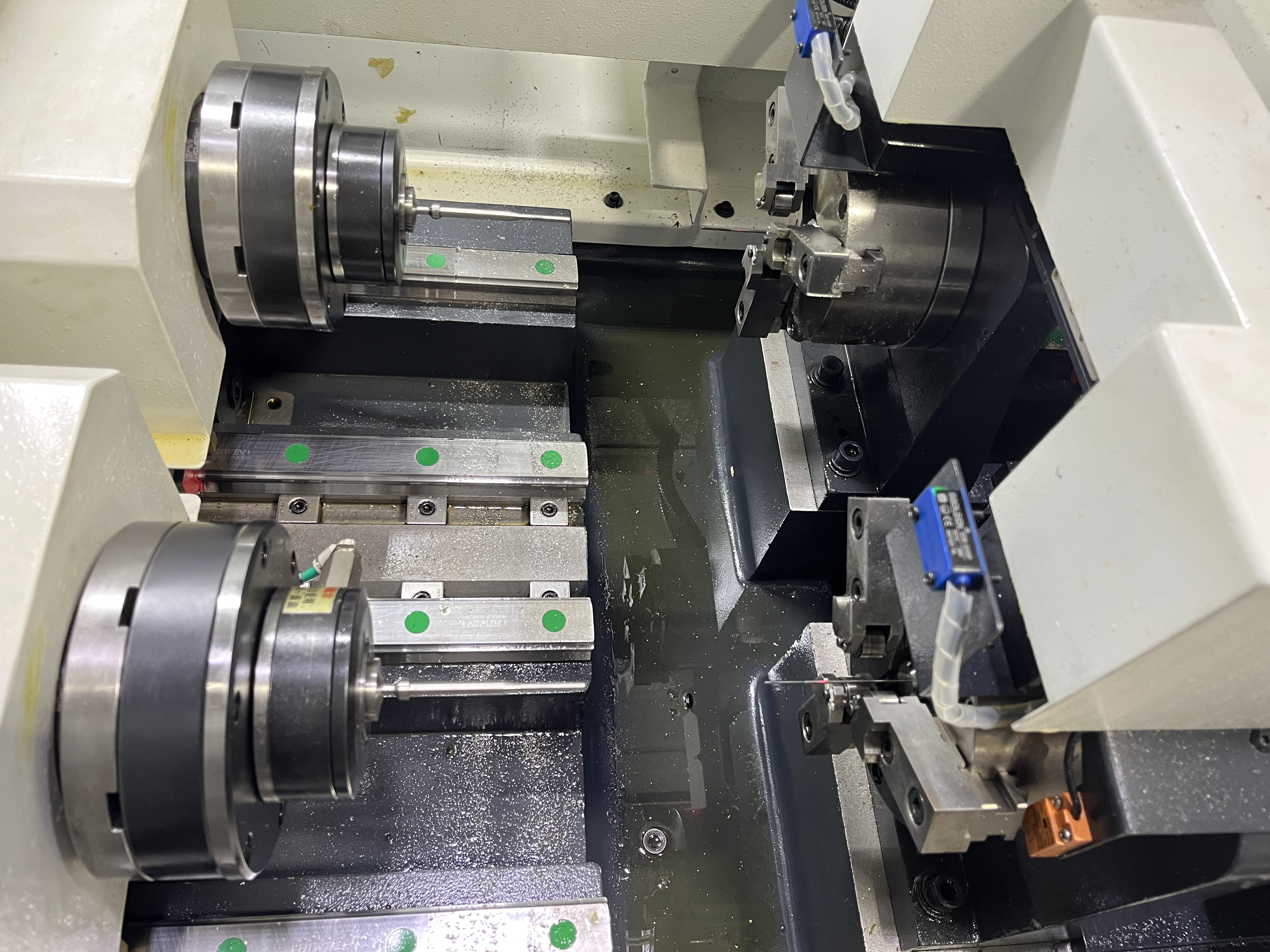
Pump components are a regular source of deep hole drilling work. Gear pumps, piston pumps, and centrifugal pumps all have components that need precise bores. The work ranges from small precision holes in pump housings to large bores in pump shafts.
I have worked on components for hydraulic pumps and centrifugal pumps. Each type has its own requirements. Here is how the common pump component categories break down in my experience:
| Pump Type | Component | Typical Bore Dia | Typical Depth | Material Grades | Tolerance Grade |
|---|---|---|---|---|---|
| Gear pump | Housing bore (gear shaft) | 20 - 50 mm | 50 - 200 mm | Cast iron (GG25), 6061-T6 Al | IT7 - IT8 |
| Gear pump | Gear bore (through-hole) | 10 - 30 mm | 30 - 100 mm | 4140, 4340 steel | IT6 - IT7 |
| Piston pump | Cylinder bore | 10 - 30 mm | 50 - 200 mm | 4140, 8620, ductile iron | IT6 - IT7 |
| Piston pump | Valve plate bore | 5 - 15 mm | 20 - 80 mm | Bronze, 316 stainless | IT7 |
| Centrifugal pump | Shaft through-hole | 10 - 30 mm | 300 - 3000 mm | 1045, 4140, 17-4PH | IT8 - IT9 |
| Centrifugal pump | Seal housing bore | 30 - 80 mm | 50 - 150 mm | Cast iron, 316 stainless | IT7 - IT8 |
| Plunger pump | Plunger bore | 20 - 60 mm | 100 - 500 mm | Duplex 2205, Inconel 625 | IT6 |
| Plunger pump | Valve body bore | 10 - 40 mm | 30 - 200 mm | 4140 QT, 17-4PH H900 | IT7 |
IT6 corresponds to roughly +/- 0.01 mm at 30 mm diameter, and IT8 is about +/- 0.03 mm. The plunger pump bores are the tightest I work on — they need IT6 because any clearance loss reduces volumetric efficiency noticeably.
Gear Pump Components
Gear pump housings need bores for the gear shafts. The bores are typically 20-50mm in diameter and 50-200mm deep. The tolerance requirements are similar to valve body work — the gear shafts need to rotate freely without excessive clearance.
The material is usually cast iron or aluminum for gear pumps. Both materials drill well with standard gun drilling parameters.
For cast iron gear pump housings:
| Parameter | Value |
|---|---|
| Cutting speed | 80-120 m/min |
| Feed rate | 0.06-0.12 mm/rev |
| Coolant pressure | 500-800 psi |
| Coolant type | Emulsion 6-8% concentration |
| Surface finish target | Ra 0.8 μm |
| Expected tool life | 50-80 m per regrind |
The finish in cast iron is naturally good due to the graphite content. I have seen as-drilled surface finishes of Ra 0.6 μm in cast iron with a sharp gun drill. The challenge with cast iron is not the finish but the abrasive wear — the graphite contains carbides that wear the drill tip over time. I check the drill tip diameter after every 20 parts and adjust the tool change interval based on the wear rate.
Piston Pump Components
Piston pumps have cylinders that need precise bores for the pistons. The bores are typically 10-30mm in diameter and 50-200mm deep. The clearance between the piston and the bore is critical for volumetric efficiency.
The material is usually steel or cast iron. Steel piston pump components need careful attention to surface finish and tolerance.
For steel piston pump bores, I use the same approach as for valve spool bores: gun drill to within 0.02mm, then hone to final size and finish.
Centrifugal Pump Shafts
Centrifugal pump shafts need through-holes for cooling or lubrication in some designs. The shafts are typically 30-80mm in diameter with a through-hole of 10-30mm. The length can be 1-3 meters depending on the pump size.
Shaft drilling for pumps is similar to general shaft work. The main requirement is straightness — the shaft rotates at motor speed, and a bent shaft causes vibration and seal wear.
Seal and Bushing Bores
Pump housings have bores for mechanical seals and bushings. These are precision bores that need to be concentric with the shaft bore. If the seal bore is off-center relative to the shaft bore, the seal leaks.
I’ve seen pump manufacturers bore the seal diameter and the shaft diameter in the same setup to guarantee concentricity. This is the best approach if the machine has the capacity to handle the full part.
Material Considerations
Pump components are made from a wide range of materials, and each one demands different parameters:
| Material | Typical Application | Cutting Speed (m/min) | Feed (mm/rev) | Coolant Pressure (psi) | Notes |
|---|---|---|---|---|---|
| Cast iron (GG25, GGG40) | Gear pump housings | 80 - 120 | 0.06 - 0.12 | 500 - 800 | High graphite content gives good finish |
| 6061-T6 aluminum | Low-pressure pump bodies | 150 - 250 | 0.08 - 0.15 | 400 - 700 | Stringy chips — use peck cycles |
| 4140 / 4340 steel | Piston cylinders, shafts | 60 - 90 | 0.04 - 0.08 | 800 - 1200 | Standard steel parameters |
| 316 stainless | Sanitary/chemical pumps | 40 - 70 | 0.03 - 0.06 | 1000 - 1500 | Work hardens — maintain feed |
| 17-4PH (H900) | High-pressure valve bodies | 30 - 50 | 0.02 - 0.05 | 1200 - 1800 | Hardened — use EP additives |
| Bronze (C932, C954) | Marine pump bushings | 100 - 180 | 0.06 - 0.12 | 400 - 700 | Soft — watch for burr formation |
| Duplex 2205 | Plunger pump components | 40 - 60 | 0.03 - 0.06 | 1000 - 1500 | Low thermal conductivity — coolant critical |
Each material requires different drilling parameters and a different coolant additive strategy. I adjust speed and feed based on the material and check the surface finish after the first hole. The coolant additives article covers the EP and anti-foam additives I use for the tougher materials like 17-4PH and duplex stainless.
Quality Standards
Pump components are inspected to several standards depending on the application. Here are the standards I work with:
| Standard | Scope | Key Requirements |
|---|---|---|
| ISO 286 (IT grades) | Bore tolerance | IT6 for plunger bores, IT7-IT8 for housing bores |
| ISO 1302 | Surface finish | Ra 0.4-0.8 μm for sealing surfaces |
| DIN 5480 | Spline bore alignment | Concentricity within 0.02 mm |
| API 610 | Centrifugal pump shafts | Shaft runout within 0.025 mm TIR |
| ASTM A536 | Ductile iron castings | Hardness 180-240 HB for pump housings |
I keep a copy of the relevant standard at the inspection station for each job. The inspector checks the critical dimensions against the standard and records the results. If a dimension is out of tolerance but within a defined rework limit, I evaluate whether rework is economical. For most pump bores, a 0.01 mm oversize bore can be saved with a reground carbide reamer, but a 0.02 mm oversize usually means scrapping the part.
The Common Factor
The common factor across all pump work is bore quality. The bore determines how well the pump performs and how long it lasts. A pump with a good bore runs efficiently for years. A pump with a poor bore loses efficiency from the start.
I focus on getting the bore right — straight, smooth, and to tolerance — regardless of the pump type or material. The data collection approach I use to track bore quality across production runs is covered in the troubleshooting data collection article. Tracking bore diameter trends by tool and material lets me predict when a tool change is needed before the bore goes out of tolerance.
Key Takeaways
- Pump components span gear pump housings, piston cylinders, centrifugal shafts, plunger bores, and valve bodies — each with specific tolerance requirements from IT6 to IT9.
- I track eight material grades for pump components: cast iron, 6061-T6 aluminum, 4140/4340 steel, 316 stainless, 17-4PH, bronze, and duplex 2205 — each requires different speed, feed, and coolant pressure.
- Plunger pump bores have the tightest tolerance (IT6, roughly +/- 0.01 mm) and need gun drilling followed by honing for final size.
- Cast iron produces good as-drilled surface finish (Ra 0.6 μm) but the graphite content causes abrasive wear on the drill tip — I check tip diameter every 20 parts.
- Pump shafts need straightness control — a bent shaft causes vibration and seal wear, and I use the data collection system to track bore diameter trends by tool and material.
- Quality is governed by ISO 286 (bore tolerance), ISO 1302 (surface finish), and API 610 (shaft runout).
- The common factor across all pump work is bore quality — a good bore means years of efficient operation, and a poor bore means losses from the start.