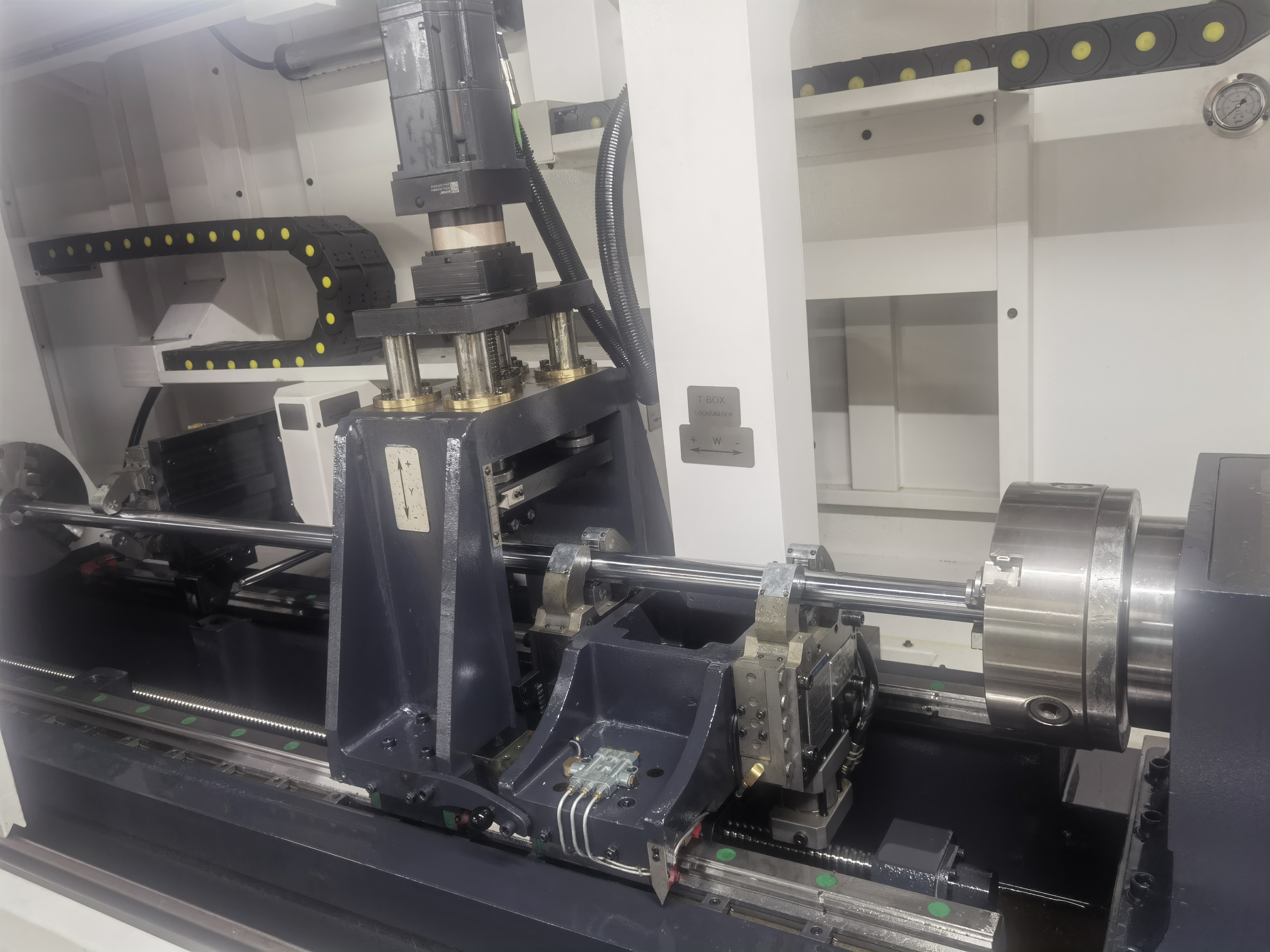
Subsea oil and gas components live at the bottom of the ocean, under thousands of meters of water and hundreds of bar of pressure. A failure down there is not something you can repair with a service truck. I have been drilling subsea components for over a decade, and the standards are higher than anything else I have encountered in machining.
This article covers what I have learned drilling deep holes in subsea valve bodies, connectors, manifolds, and christmas tree components. If you are new to subsea work, start with my overview of oil and gas deep hole drilling and the deep hole drilling guide for stainless steel.
Typical Subsea Components
Subsea production systems are assemblies of pressure-containing components that sit on the seafloor. The deep hole drilling work shows up in several critical parts.
Valve bodies. Subsea gate valves and ball valves control the flow of hydrocarbons from the well. The bores range from 50mm to 300mm in diameter, with depths of 200mm to 800mm. What sets subsea valves apart is the wall thickness – they are built heavier than surface valves because the external pressure at 3,000 meters water depth adds to the internal operating pressure. A subsea valve body might have 50mm or more of wall thickness, which means the BTA drilling pass goes through solid material for a long time before it reaches the internal cavity.
Connectors. Subsea connectors join wellheads, trees, and flowlines together. The most common type I drill is the mandrel connector, which has a large through-bore of 200-400mm for the production flow. These connectors need a smooth bore finish because they seal with elastomer or metal-to-metal seals. I have held 0.8 Ra on a 350mm bore in super duplex stainless, and it required every bit of the machine’s rigidity.
Manifolds. Subsea manifolds route production from multiple wells into a single flowline. The manifold body is a large block of steel with multiple intersecting bores. The challenge here is intersecting hole geometry – a manifold might have a 200mm through-bore that intersects with a 100mm lateral bore at a 90-degree angle. The intersection creates an interrupted cut similar to a valve body cavity, but with more complex chip evacuation.
Christmas trees. The christmas tree sits on top of the wellhead and controls production flow. It contains multiple valves, chokes, and sensors in a compact assembly. The tree body has several deep bores for the production bore, annulus bore, and chemical injection lines. These bores are typically 50-150mm and can be up to one meter deep. The tree is the most expensive single subsea component, and scrap is not an option.
Materials for Subsea Service
Subsea components are made from corrosion-resistant alloys because they have to survive decades of exposure to seawater and produced fluids without degrading. I have worked with the following materials most frequently.
Duplex stainless steel (UNS S31803 / S32205). This is the workhorse material for subsea components. Duplex has roughly 50-50 ferrite-austenite microstructure, which gives it twice the yield strength of 316L and excellent resistance to chloride stress corrosion cracking. The challenge with drilling duplex is its tendency to work-harden. I have written a detailed breakdown of this in the stainless steel deep hole drilling guide, but the short version is: keep the tool engaged and never let the feed drop below 0.08 mm/rev.
Super duplex stainless steel (UNS S32750 / S32760). Super duplex takes the alloy content higher – more chromium, molybdenum, and nitrogen – for even better corrosion resistance. The PREN (pitting resistance equivalent number) of super duplex is above 40, compared to 35 for standard duplex. Super duplex is harder to drill than standard duplex because the higher alloy content increases the shear strength. I typically reduce cutting speed by 10-15% compared to standard duplex.
Inconel 625 and 718 (UNS N06625 / N07718). Nickel-based alloys are used for the most critical sealing surfaces and for components that see the highest temperatures and pressures. Inconel is gummy and work-hardens aggressively. I use carbide grades with a sharp edge and higher rake angle to reduce cutting forces. Coolant pressure needs to be above 500 psi to prevent chip welding.
17-4 PH stainless steel (UNS S17400). This precipitation-hardening stainless is used for valve stems, actuator components, and fasteners. In the H1150 condition it is machinable, but in the H900 condition it is extremely hard and abrasive. I always verify the heat treat condition before quoting the job.
NACE MR0175 Compliance
Every subsea component I have drilled must comply with NACE MR0175 / ISO 15156, which sets the requirements for materials used in sour (hydrogen sulfide) service. H2S exposure causes sulfide stress cracking (SSC) in susceptible materials, and a cracked subsea component can cause a catastrophic release.
NACE compliance affects deep hole drilling in two ways. First, the material certification must show that the alloy chemistry and hardness meet NACE requirements. For duplex stainless, the hardness limit is typically 32 HRC maximum. I have had parts rejected because a work-hardened zone from a drilling pass exceeded the hardness limit. This is why I keep feeds and speeds aggressive enough to avoid dwell marks.
Second, the surface finish must be free of machining defects that could act as stress concentrators. NACE MR0175 requires a maximum surface roughness of Ra 1.6 micrometers on all wetted surfaces. I have seen a 0.5mm deep tool mark on a bore wall cause a crack initiation in hydrostatic testing. The bore then had to be welded and re-machined.
I always include NACE compliance in the inspection plan before starting the job. The documentation requirements include material test reports (MTRs) with full chemistry and mechanical properties, hardness surveys, and surface roughness measurements.
Drilling Parameters for Duplex Stainless
Duplex stainless is the most common subsea material and the one that gives most shops trouble. Here are the parameters I use after years of dialing them in.
| Material | Cutting Speed (m/min) | Feed Rate (mm/rev) | Coolant Pressure (psi) | Coolant Type | Tool Grade |
|---|---|---|---|---|---|
| Duplex S31803/S32205 | 55-70 | 0.10-0.18 | 400-600 | Oil, high EP | Fine-grain carbide, TiAlN |
| Super Duplex S32750/S32760 | 45-60 | 0.08-0.15 | 450-650 | Oil, high EP | Submicron carbide, AlTiN |
| Inconel 625 | 25-40 | 0.06-0.12 | 500-700 | Oil, extreme pressure | Micrograin carbide, AlTiN |
| Inconel 718 (annealed) | 20-35 | 0.05-0.10 | 500-700 | Oil, extreme pressure | Micrograin carbide, AlTiN |
| 17-4 PH (H1150) | 60-80 | 0.10-0.18 | 350-500 | Oil, high EP | Fine-grain carbide, TiAlN |
| 17-4 PH (H900) | 35-50 | 0.08-0.14 | 400-550 | Oil, high EP | Submicron carbide, AlTiN |
The key variable with duplex is the feed rate. If the feed drops too low, the cutting edge rubs instead of shearing, and the surface work-hardens instantly. I have measured a work-hardened layer of 0.15mm depth on a duplex bore where the feed stalled during a tool change. That layer had a hardness of 38 HRC – well above the NACE limit. The only fix was a full finish-boring pass at the correct feed to remove the hardened layer.
Coolant choice matters. I use high-EP (extreme pressure) oil for duplex and super duplex. Water-soluble coolant does not provide enough lubricity at the cutting edge for these materials. The EP additives form a sulfur-based boundary layer that prevents chip welding at the high temperatures in the cutting zone.
Quality and Inspection Requirements
The inspection requirements for subsea components are more extensive than for any other oil and gas work I have done. Every bore gets inspected, and every inspection gets documented with a traceable serial number.
| Inspection Method | What It Detects | Acceptance Criteria | Frequency |
|---|---|---|---|
| Ultrasonic wall thickness | Minimum wall, laminations | Per engineering drawing + 1mm corrosion allowance | 100% of pressure-containing bores |
| Magnetic particle inspection (MPI) | Surface cracks, grinding burns | No linear indications > 1mm | 100% of wetted surfaces |
| Dye penetrant (PT) | Surface cracks in non-ferrous | No indications | 100% of seal surfaces |
| Hydrostatic pressure test | Gross leaks, structural weakness | 1.5x rated pressure, zero drop in 30 min | 100% of assembled components |
| Dimensional CMM | Bore diameter, roundness, taper | Per drawing, typically H7 or tighter | 100% of critical bores |
| Surface roughness profilometer | Ra finish | Ra 1.6 um max, seal areas Ra 0.8 um | 100% of pressure-containing bores |
| Hardness survey | Work-hardening, material verification | Per NACE MR0175 limits | Each bore quadrant at 3 depths |
Ultrasonic testing requires a smooth bore surface to get a reliable reading. I have found that an Ra finish of 3.2 or better is necessary for consistent UT coupling. If the bore is too rough, the UT transducer loses contact with the surface and gives false readings. I always finish-bore to at least Ra 1.6 before the UT inspection.
Testing Requirements
Testing is where the real cost of subsea work shows up. Every pressure-containing component gets hydrostatically tested at 1.5 times the design pressure. For a 10,000 psi rated subsea tree, that means 15,000 psi in the test. I have seen components deform under hydrostatic test pressure even though they passed dimensional inspection. The deformation usually traces back to an uneven wall thickness from an off-center bore.
The hydrostatic test procedure I follow:
- Fill the component with clean water and vent all air pockets
- Pressurize to 50% of test pressure and hold for 5 minutes for initial check
- Increase to 100% of test pressure (1.5x rated) and hold for 30 minutes
- Monitor pressure drop – zero drop is required
- Depressurize and visually inspect all external surfaces for weeping or deformation
NDT inspection is done both before and after hydrostatic testing. The post-test inspection catches any cracks that opened during the pressure cycle. I have seen MPI reveal a subsurface crack after hydrostatic testing that was invisible on the pre-test inspection.
Gas testing is sometimes required in addition to hydrostatic testing. For gas service components, a pneumatic test at 110% of rated pressure using nitrogen is performed. This is a more severe test because gas stores more energy, and the safety protocols are correspondingly strict.
Key Takeaways
- Subsea oil and gas components require the highest standards of any deep hole drilling I have done – every bore is pressure-containing and failure is not an option.
- Duplex and super duplex stainless steels are the most common materials; they work-harden aggressively if feed rate drops below 0.08 mm/rev, which also risks exceeding the NACE MR0175 hardness limit of 32 HRC.
- Inspection is 100% across the board: ultrasonic wall thickness, MPI, dye penetrant, hydrostatic testing, CMM dimensional inspection, and surface roughness measurement are all mandatory on pressure-containing bores.
- Hydrostatic testing at 1.5x rated pressure is the final gate; off-center bores that cause uneven wall thickness often show up as deformation during this test.
- NACE MR0175 compliance governs material selection, hardness limits, and surface finish requirements – build the inspection plan around NACE requirements before the first chip is cut.
- Use high-EP oil coolant, not water-soluble, for duplex and super duplex drilling, and monitor spindle load constantly for the first sign of work-hardening.