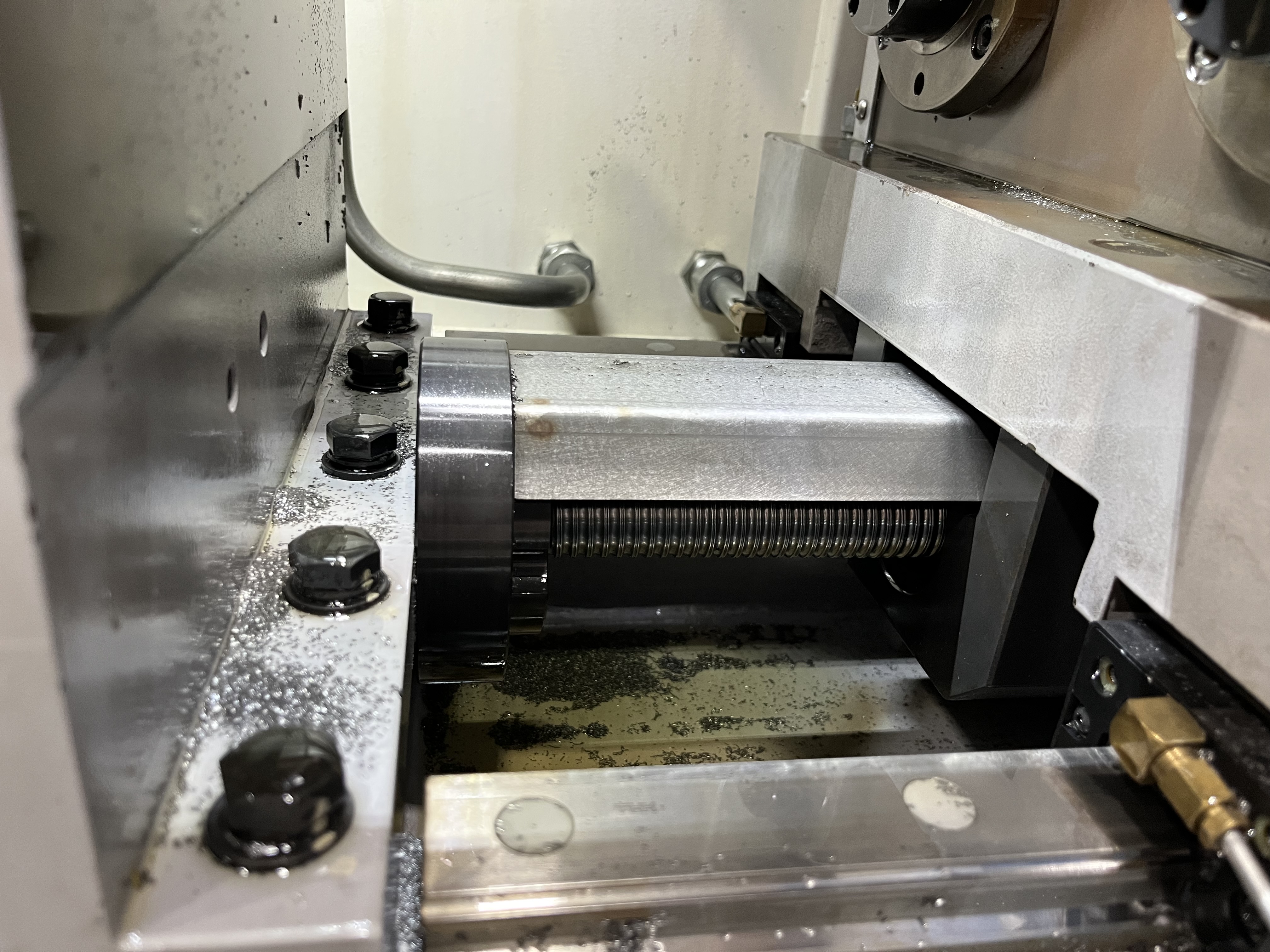
Injection molding machine tie bars are long, heavy-duty rods that guide the moving platen and carry the clamping force. Some tie bars need a through-hole for the clamping mechanism or for lubrication. In my experience, the through-hole concentricity is the single most critical factor determining whether the tie bar performs reliably over years of cycling.
Tie Bar Specifications and Material Properties
A typical tie bar is 2-5 meters long with a 20-50mm through-hole. The material is high-strength steel like 42CrMo4, often induction-hardened on the OD. The drilling is done before hardening because the hardened surface is too tough for efficient drilling.
I have worked with several grades of tie bar steel. Here is a comparison of the most common ones:
| Grade | Tensile Strength (MPa) | Hardness (HB) | Weldability | Typical Application |
|---|---|---|---|---|
| 42CrMo4 | 900-1100 | 280-320 | Fair | Standard injection molding machines |
| 40CrNiMo6 | 1000-1200 | 300-350 | Poor | High-clamp-force machines |
| 38CrMoAl | 850-1000 | 260-300 | Good | Nitrided tie bars |
| C45 (1045) | 600-800 | 200-250 | Good | Small machines, low-cost builds |
For 42CrMo4, I have found that keeping the surface speed below 90 m/min prevents excessive tool wear while maintaining a stable chip formation. Above that speed, the carbide inserts start breaking down after just 3-4 meters of drilling.
Drilling Parameters and Tool Selection
For a 30mm through-hole in tie bar steel, my standard parameters are:
| Parameter | Value | Notes |
|---|---|---|
| Cutting speed | 70-90 m/min | Lower end for harder grades |
| Feed rate | 0.05-0.08 mm/rev | Adjusted based on chip form |
| Coolant pressure | 800-1200 psi | Must be sufficient for chip evacuation |
| Coolant flow | 80-120 L/min | Minimum for 30mm bore |
| Process | Gun drilling | Preferred for 20-50mm diameters |
I use gun drilling for tie bar through-holes because the diameters fall in the 20-50mm range where gun drilling is most efficient. The single-lip gun drill produces a consistent bore diameter and good surface finish. I use a carbide gun drill head brazed onto a steel shank, with coolant holes that direct high-pressure oil to the cutting edge.
The gun drill geometry I use includes a 30-degree point angle and a 10-degree clearance angle. These angles work well for the alloy steel grades common in tie bar manufacturing. The chip breaker is ground into the cutting face to produce small, broken chips that evacuate easily.
Concentricity and Setup Methods
The main challenge is maintaining concentricity over the length. The through-hole needs to be centered within 0.2mm of the bar axis. If the hole is off-center, the tie bar will be unbalanced and can cause vibration during machine operation.
I rotate the tie bar during drilling while the tool is stationary. The rotation keeps the hole centered. I use steady rests at 1.5-meter intervals to prevent the bar from sagging under its own weight. For a 4.5-meter bar, I position steady rests at 1.5m, 3.0m, and 4.5m from the drilling head.
Alignment procedure at each steady rest:
- Set the dial indicator on the bar surface near the steady rest
- Rotate the bar by hand and note the runout
- Adjust the steady rest until runout is below 0.03mm
- Lock the steady rest and recheck
- Repeat for all steady rests
I have found that bar sag is the most common cause of concentricity failure. A 4-meter bar weighing 800 kg will sag by 0.15-0.25mm at its midpoint if supported only at the ends. The steady rests eliminate this sag and keep the bar straight.
Hydraulic Bore Requirements and Surface Finish
The surface finish in the bore is typically Ra 1.6um as-drilled. If the hole is for a hydraulic clamping mechanism, the finish needs to be Ra 0.8um or better. I use a burnishing pass to improve the finish if needed.
| Requirement | Standard Tie Bar | Hydraulic Tie Bar |
|---|---|---|
| Surface finish (Ra) | 1.6 um | 0.8 um |
| Diameter tolerance | +/- 0.1 mm | +/- 0.05 mm |
| Concentricity | 0.2 mm | 0.1 mm |
| Roundness | 0.05 mm | 0.03 mm |
For hydraulic tie bars, I do a semi-finish bore with a reamer followed by a burnishing pass. The reamer removes 0.1-0.2mm and corrects any diameter variation from the gun drilling pass. The burnishing tool then cold-works the surface to the final finish and diameter.
Inspection and Quality Control
After drilling, I check the bore diameter at both ends and mid-length. The diameter should be consistent within 0.05mm over the full length. A tapered bore causes uneven stress distribution in the tie bar under load.
My inspection checklist:
- Bore diameter at three positions using a three-point internal micrometer
- Bore straightness using a laser alignment system
- Surface finish using a portable profilometer
- Wall thickness using ultrasonic testing at six positions around the circumference
I record all measurements in a data sheet that accompanies the tie bar through production. This traceability is important for quality audits and for identifying process trends over time.
Key Takeaways
- Gun drilling at 70-90 m/min with 800-1200 psi coolant is the standard process for tie bar through-holes in the 20-50mm range
- Concentricity within 0.2mm requires workpiece rotation and steady rests spaced at 1.5-meter intervals with sub-0.03mm runout alignment
- Hydraulic tie bars demand a two-step process: reaming followed by burnishing to achieve Ra 0.8um
- Material grade selection (42CrMo4 vs. 40CrNiMo6) directly affects tool life and requires speed adjustments
- Consistent diameter within 0.05mm over the full length prevents uneven stress distribution under clamping loads