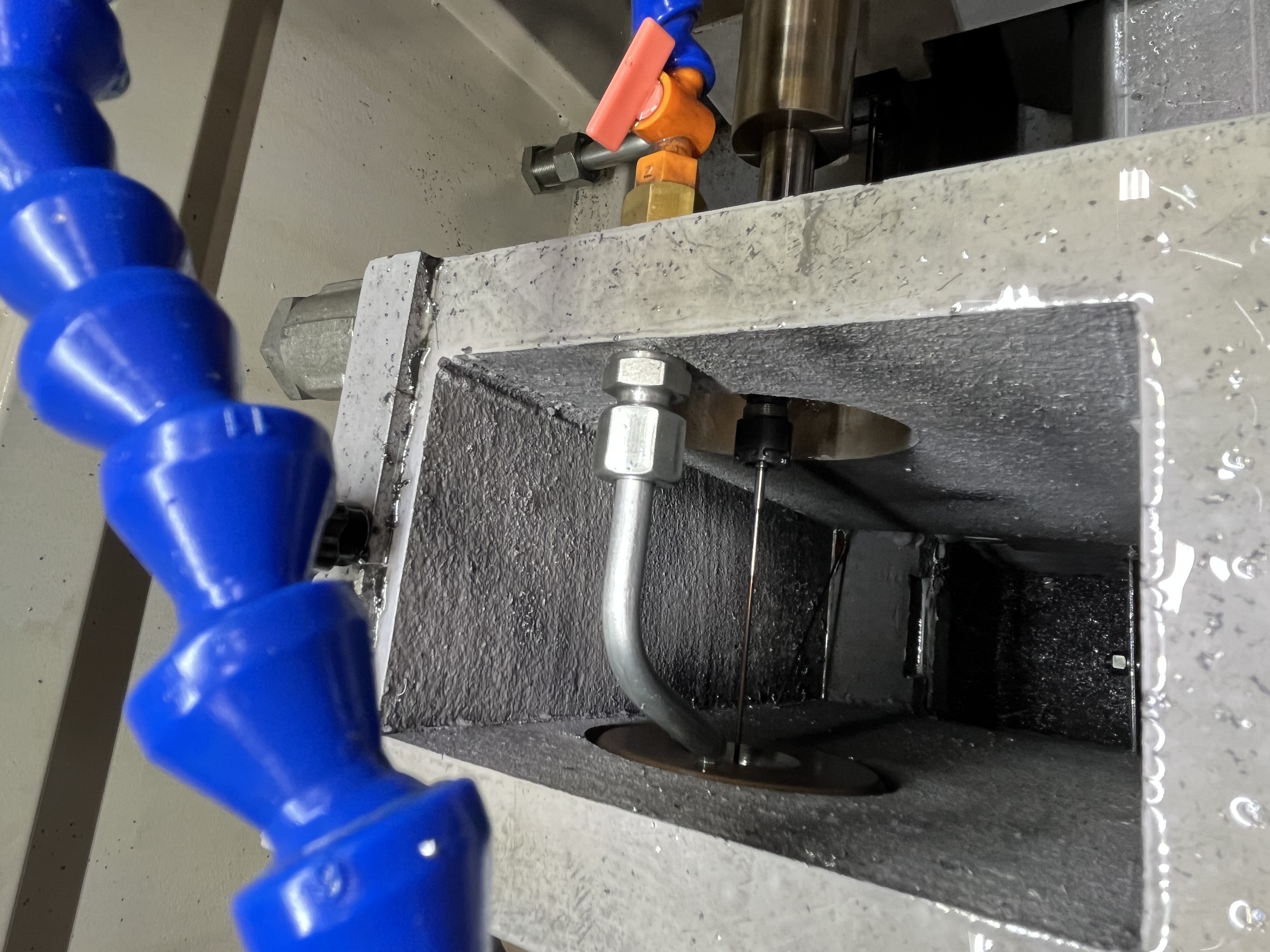
Railway wheel sets consist of two wheels pressed onto an axle. The wheel has a bore that is precision-machined to an interference fit with the axle. The bore tolerance determines whether the press fit holds the wheel securely in service. In my experience, the boring operation is the most quality-critical step in wheel set manufacturing because once the wheel is pressed onto the axle, an incorrect bore cannot be corrected without scrapping components.
Wheel Specifications and Material Grades
A typical freight car wheel bore is 120-180mm diameter through 120-150mm of wheel hub. The material is cast or forged steel with a hardness of 250-350 HB. The bore tolerance is typically +0.05mm for the press fit.
I have worked with several wheel grades. Here is a comparison:
| Wheel Grade | Material | Hardness (HB) | Application | Bore Difficulty |
|---|---|---|---|---|
| Class B | Forged steel | 250-300 | Freight cars (standard) | Low |
| Class C | Forged steel | 300-350 | Freight cars (heavy load) | Medium |
| Class D | Forged steel | 320-380 | Locomotives | Medium-High |
| R8T | Cast steel | 280-340 | Passenger cars | Medium |
| ER8 | Forged steel | 260-300 | High-speed rail | Low |
For harder wheel grades like Class D, I reduce cutting speed by 10-15% and use a tougher carbide grade (ISO K20-K30) to handle the abrasive wear. The surface finish requirement is the same across all grades, but the harder materials require sharper cutting edges and more frequent insert changes.
Boring Parameters and Tool Selection
For boring a wheel set bore, my standard parameters are:
| Parameter | Rough Boring | Finish Boring |
|---|---|---|
| Cutting speed | 70-90 m/min | 80-100 m/min |
| Feed rate | 0.12-0.18 mm/rev | 0.08-0.12 mm/rev |
| Depth of cut | 0.5-1.0 mm | 0.3-0.5 mm |
| Coolant pressure | 300-500 psi | 300-500 psi |
| Cycle time (per bore) | 1-2 min | 1-2 min |
I use a single-point boring bar with a TiN-coated insert for the finish pass. The finish pass removes 0.3-0.5mm and produces the final diameter. The surface finish target is Ra 1.6um.
The boring bar diameter I choose is based on the bore diameter. For a 150mm bore, I use a 50mm diameter boring bar with a steel shank. The bar overhang is kept to 200mm (maximum) to minimize deflection. If the bar overhang exceeds 200mm, vibration and chatter become visible in the surface finish.
I have tested different insert coatings for wheel boring:
| Insert Coating | Tool Life (bores) | Surface Finish | Best For |
|---|---|---|---|
| TiN (titanium nitride) | 80-120 | Ra 1.2-1.6um | General purpose, most grades |
| TiAlN (titanium aluminum nitride) | 120-180 | Ra 1.0-1.4um | Class D, locomotive wheels |
| CBN (cubic boron nitride) | 500-800 | Ra 0.6-1.0um | Hardened wheels (>350 HB) |
| Ceramic | 200-300 | Ra 1.0-1.4um | High-speed finishing |
TiN-coated inserts are my default for standard freight car wheels. I switch to TiAlN for harder wheel grades where tool life becomes a cost factor. CBN inserts are expensive but justify their cost on high-volume production lines.
Fixturing and Roundness Control
The main challenge is maintaining roundness. A wheel that is clamped unevenly in the fixture will distort, and the bore will be out of round. I use a three-jaw fixture that clamps on the wheel tread with equal force.
I have compared fixture types for wheel boring:
| Fixture Type | Roundness Achievable | Clamping Distortion | Setup Time |
|---|---|---|---|
| Three-jaw on tread | 0.015-0.025mm | Low | 2-3 min |
| Hydraulic chuck on tread | 0.010-0.020mm | Very low | 3-4 min |
| Face plate with clamps | 0.020-0.035mm | Medium | 4-5 min |
| Expanding mandrel on bore | 0.005-0.015mm | None | 5-6 min |
The expanding mandrel gives the best roundness, but it requires a pre-machined bore, which adds an operation. For most wheel production, the three-jaw tread clamp provides acceptable roundness with the shortest cycle time.
I have developed a clamping procedure that minimizes distortion:
- Clean the wheel tread surface with a wire brush to remove scale
- Position the wheel in the fixture with the hub facing the boring bar
- Apply clamping force gradually, alternating between the three jaws
- Check runout on the hub OD with a dial indicator
- If runout exceeds 0.05mm, release and reposition
Inspection and Quality Assurance
After boring, I check the bore diameter at three depths and two orientations. The roundness should be within 0.02mm. The bore should also be perpendicular to the wheel face within 0.05mm.
My inspection protocol for each wheel bore:
- Bore diameter: measured at top, middle, and bottom of the hub (three depths)
- Roundness: measured at two orientations, 90 degrees apart, at each depth
- Perpendicularity: measured between the bore axis and the wheel face
- Surface finish: measured with a portable profilometer at one location
- Visual inspection: check for chatter marks, tool marks, or surface defects
I also check the bore for any signs of chatter or tool marks. A rough bore surface can cause the wheel to shift on the axle during service.
The most common quality issues I see in wheel boring:
- Chatter marks from excessive boring bar overhang (over 200mm)
- Out-of-round from uneven clamping (corrected by the three-jaw procedure above)
- Taper from tool deflection at the bottom of the bore (corrected by reducing feed rate)
- Surface roughness from worn inserts (prevented by tracking tool life in bores)
Axle Matching and Press Fit Assembly
The bore diameter is recorded for each wheel and matched to the axle diameter. The interference fit is typically 0.15-0.25mm for freight car wheels.
My axle matching procedure:
- Measure each axle journal diameter at three positions along its length
- Sort axles by diameter into 0.02mm bands
- Sort wheel bores by diameter into 0.02mm bands
- Match wheels to axles such that the interference is between 0.15-0.25mm
- Record the match in the production data sheet
For high-speed rail wheels (passenger trains over 200 km/h), the interference fit tolerance is tighter at 0.18-0.22mm. The bore roundness must be below 0.015mm, and the perpendicularity must be below 0.03mm. I use a hydraulic expanding mandrel fixture for high-speed rail wheels to achieve these tolerances consistently.
Key Takeaways
- Three-jaw tread clamping with a graduated application sequence produces roundness within 0.015-0.025mm for standard freight wheels
- TiN-coated carbide inserts deliver 80-120 bores per edge in Class B-C wheel steel at 70-90 m/min
- Boring bar overhang must be limited to 200mm maximum to prevent chatter
- Axle matching with 0.02mm diameter bands ensures interference fits between 0.15-0.25mm
- High-speed rail wheels require hydraulic expanding mandrel fixturing and tighter tolerances (roundness below 0.015mm, perpendicularity below 0.03mm)