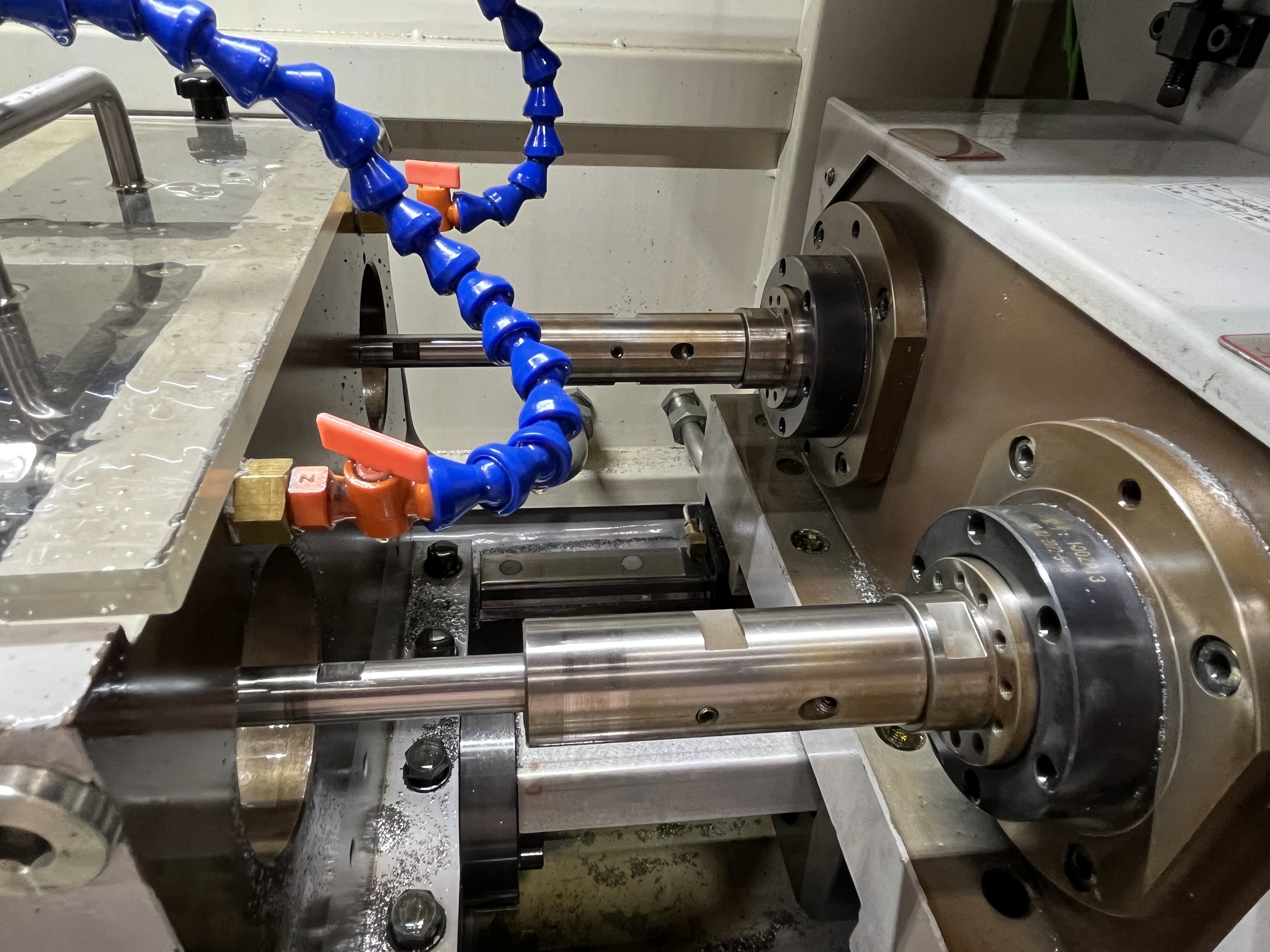
Coolant filtration is essential for deep hole drilling. Chips that recirculate through the coolant will damage the drill edge and score the bore surface. I have designed and modified filtration systems for dozens of machines, and the system design has a direct impact on tool life, surface finish, and machine reliability. A well-designed filtration system delivers clean coolant consistently and requires minimal operator attention.
Filter Type Comparison
There are several filtration technologies available, and choosing the right one depends on your material, chip volume, and coolant pressure requirements. Here is how the main types compare based on my experience.
| Filter Type | Micron Rating | Ferrous Only? | Consumable Cost | Capital Cost | Maintenance | Best For |
|---|---|---|---|---|---|---|
| Magnetic separator | <1 micron (ferrous) | Yes | None | $3,000-$8,000 | Low — clean scrapers | Steel/cast iron high-volume |
| Paper band filter | 10-50 micron | No | Paper roll: $50-$200 each | $2,000-$6,000 | Medium — paper changes | General purpose |
| Cartridge filter | 5-50 micron | No | Cartridge: $10-$50 each | $1,000-$3,000 | Medium — change at 10 psi drop | Low-volume, precision |
| Centrifuge | 1-5 micron | No | None | $8,000-$20,000 | High — manual cleaning | High-precision, fine finishing |
| Hydrocyclone | 10-30 micron | No | None | $2,000-$5,000 | Low — no moving parts | Roughing, pre-filter |
| Candle filter | 5-10 micron | No | Filter elements: $50-$150 | $4,000-$10,000 | Low — backwashable | Polishing, closed-loop |
The two-stage combination I recommend for most deep hole drilling applications is a magnetic separator followed by a 10-20 micron paper band filter. This combination handles high chip volumes and delivers coolant clean enough for most drilling operations. The magnetic separator removes about 90 percent of the ferrous load for free, and the paper band handles the rest.
Three-Stage Filtration Design
The filtration system I recommend has three stages, each removing progressively smaller particles. The three-stage design balances filter life and filtration quality. Skipping a stage overloads the downstream filters and increases maintenance frequency.
| Stage | Filter Type | Particle Removal | Flow Capacity | Maintenance Interval | Cost |
|---|---|---|---|---|---|
| Stage 1 | Magnetic separator | Ferrous chips down to 100 microns | Full flow | Clean daily | $3,000 - $8,000 |
| Stage 2 | Paper band or cartridge filter | 20 - 50 microns | Full flow | Paper: roll lasts 1-4 weeks; Cartridge: change at 10 psi drop | $2,000 - $6,000 |
| Stage 3 | Polishing filter (optional) | 5 - 10 microns | 10-20% of full flow | Change at 15 psi drop | $1,000 - $3,000 |
Stage 1 is a magnetic separator that removes ferrous chips from the return coolant. The magnetic separator uses rotating magnetic discs or a magnetic conveyor belt to pull the ferrous chips out of the coolant flow. The chips are scraped off the magnets and deposited into a chip bin.
The magnetic separator removes most of the chip load before the coolant reaches the Stage 2 filter. This extends the life of the paper band or cartridge filter by 50 to 100 percent. I have measured the chip removal efficiency of a magnetic separator at over 90 percent for ferrous chips above 100 microns. High-performance magnetic separators using neodymium rare-earth magnets can capture ferrous particles down to sub-micron sizes.
Stage 2 is a paper band filter or cartridge filter that removes particles down to 20 to 50 microns. The choice between paper band and cartridge depends on the chip volume and the required filtration level. Paper band filters are better for high chip volumes because the media advances automatically when the pressure drop triggers the float switch. Cartridge filters are better for low-volume applications where the simplicity of a disposable element outweighs the need for frequent changes.
Stage 3 is a polishing filter that removes particles down to 5 to 10 microns for high-precision work. I use the polishing filter only for the coolant flow that goes to the drill, not for the full system flow. The polishing filter extends the life of the coolant and improves the surface finish on precision parts. For applications requiring micron-level surface finishes, a centrifuge or candle filter in the Stage 3 position provides the best results.
Filter Sizing Calculation
The filter size is determined by the coolant flow rate. I size the filter to handle at least 110 percent of the maximum pump flow rate at the rated pressure drop. A filter that is undersized will clog quickly and reduce coolant flow to the drill.
Here is the sizing formula I use:
- Paper band filter area = (Pump flow rate in L/min) / 100 = minimum square meters
- Cartridge filter rating = 20 micron for general deep hole drilling; 10 micron for precision
- Connection size = Match the pump outlet connection or go one size larger to minimize restriction
| Pump Flow Rate | Minimum Filter Area (Paper Band) | Minimum Filter Rating (Cartridge) | Connection Size |
|---|---|---|---|
| 30 L/min | 0.5 square meters | 20 micron | 1 inch |
| 50 L/min | 0.8 square meters | 20 micron | 1.25 inch |
| 100 L/min | 1.5 square meters | 20 micron | 1.5 inch |
| 200 L/min | 3.0 square meters | 20 micron | 2 inch |
| 400 L/min | 5.0 square meters | 20 micron | 2.5 inch |
The filter pressure drop indicates when the filter needs cleaning or replacement. I change the filter when the pressure drop exceeds 10 psi (0.7 bar) over the clean filter reading. I monitor the pressure drop weekly and note any trends. A gradual increase in pressure drop over time is normal as the filter loads. A sudden increase indicates a large volume of chips or debris entering the filter at once.
I install a differential pressure gauge with a dial indicator that shows the pressure drop across the filter. The gauge is mounted in a visible location so the operator can check it during the daily inspection. Some gauges have a switch contact that triggers an alarm on the machine control when the pressure drop exceeds the set point.
System Design Guide
I follow these design rules for every filtration system I build or modify:
- Place the magnetic separator before the paper filter. The magnetic separator catches the big stuff first, which doubles the life of the paper media. This is the single most cost-effective design decision.
- Use gravity flow through the paper filter whenever possible. Gravity-fed paper band filters are simpler and more reliable than pressure-fed systems. The coolant flows by gravity through the paper and the chips form a filter cake that traps finer particles.
- Size the tank for residence time. The tank capacity should be 5 to 10 times the pump flow rate per minute. This gives the coolant time to cool and fine particles time to settle. A 50 L/min pump needs a 250-500 liter tank minimum.
- Install the differential pressure gauge on the return line, not the pressure line. The return line gauge shows the filter condition before the coolant enters the pump, which protects the pump from running dry.
- Route the return coolant through a stilling chamber. A stilling chamber above the coolant level in the first tank compartment prevents the return flow from disturbing settled chips.
Cost Comparison by System Type
I built this cost comparison table based on my experience with various system configurations. The costs include installation, not just hardware.
| System Type | Initial Cost | Annual Consumable Cost | Annual Maintenance Hours | Typical Lifespan |
|---|---|---|---|---|
| Magnetic separator only | $5,000-$10,000 | $0 | 20 hours | 10-15 years |
| Paper band filter only | $3,000-$7,000 | $500-$2,000 | 40 hours | 5-10 years |
| Magnetic + paper band | $8,000-$15,000 | $300-$1,000 | 30 hours | 10-15 years |
| Cartridge filter only | $1,000-$4,000 | $1,000-$3,000 | 50 hours | 3-5 years |
| Magnetic + paper + polishing | $10,000-$20,000 | $500-$1,500 | 40 hours | 10-15 years |
| Centrifuge system | $15,000-$30,000 | $200-$500 | 60 hours | 8-12 years |
The magnetic separator plus paper band combination gives the best return on investment for most shops. The centrifuge system is only worth the cost for shops doing high-precision work where coolant clarity directly affects part quality.
Maintenance Schedule
| Component | Frequency | Action |
|---|---|---|
| Magnetic separator scraper | Daily | Remove accumulated chips from scraper blade |
| Paper band media | Weekly | Check remaining roll length, advance if pressure drop is high |
| Differential pressure gauge | Weekly | Record reading in log |
| Cartridge filter | At 10 psi drop | Replace cartridge |
| Sump/tank sludge level | Monthly | Check and remove if accumulated |
| Polishing filter | At 15 psi drop | Replace filter element |
| Tank clean-out | Annually | Drain, scrub, refill |
Annual Coolant Tank Cleaning
I clean the coolant tank annually. The tank accumulates fine particles and sludge that the filter system does not catch. The sludge builds up on the bottom of the tank and provides a breeding ground for bacteria. Over time, the sludge reduces the effective tank capacity and degrades the coolant quality.
The cleaning procedure starts with draining the tank completely. I pump the old coolant into waste drums for disposal following local environmental regulations. After draining, I remove the sludge from the bottom of the tank using a plastic scraper and a wet vacuum.
I wash the tank interior with a detergent solution and rinse thoroughly with clean water. All baffle plates and the tank interior surfaces are scrubbed to remove any biofilm or residue. The tank is dried completely before refilling with fresh coolant.
After cleaning, I fill the tank with fresh coolant at the correct concentration and run the system for 10 minutes to circulate the coolant through the filters before drilling any parts.
For more on coolant system maintenance, see my guides on coolant pump troubleshooting and coolant biocide types and application schedule.
Key Takeaways
- A three-stage filtration system — magnetic separator, paper band or cartridge filter (20-50 micron), and polishing filter (5-10 micron) — provides the best balance of filter life and coolant quality.
- The magnetic separator removes over 90 percent of ferrous chips above 100 microns and extends the Stage 2 filter life by 50 to 100 percent.
- The best value for most shops: magnetic separator plus 10-20 micron paper band filter at $8,000-$15,000 installed.
- I size the filter for 110 percent of the maximum pump flow rate and change the filter when the pressure drop exceeds 10 psi over the clean reading.
- The coolant tank should have a three-compartment baffle system with a capacity 5 to 10 times the pump flow rate per minute to allow chip settling and coolant cooling.
- Annual coolant tank cleaning removes accumulated sludge and biofilm that degrade coolant quality and promote bacterial growth.
- A differential pressure gauge with a visible dial and alarm contact allows the operator to monitor filter condition during daily inspections.
- For related reading, see coolant pump troubleshooting and coolant biocide types.