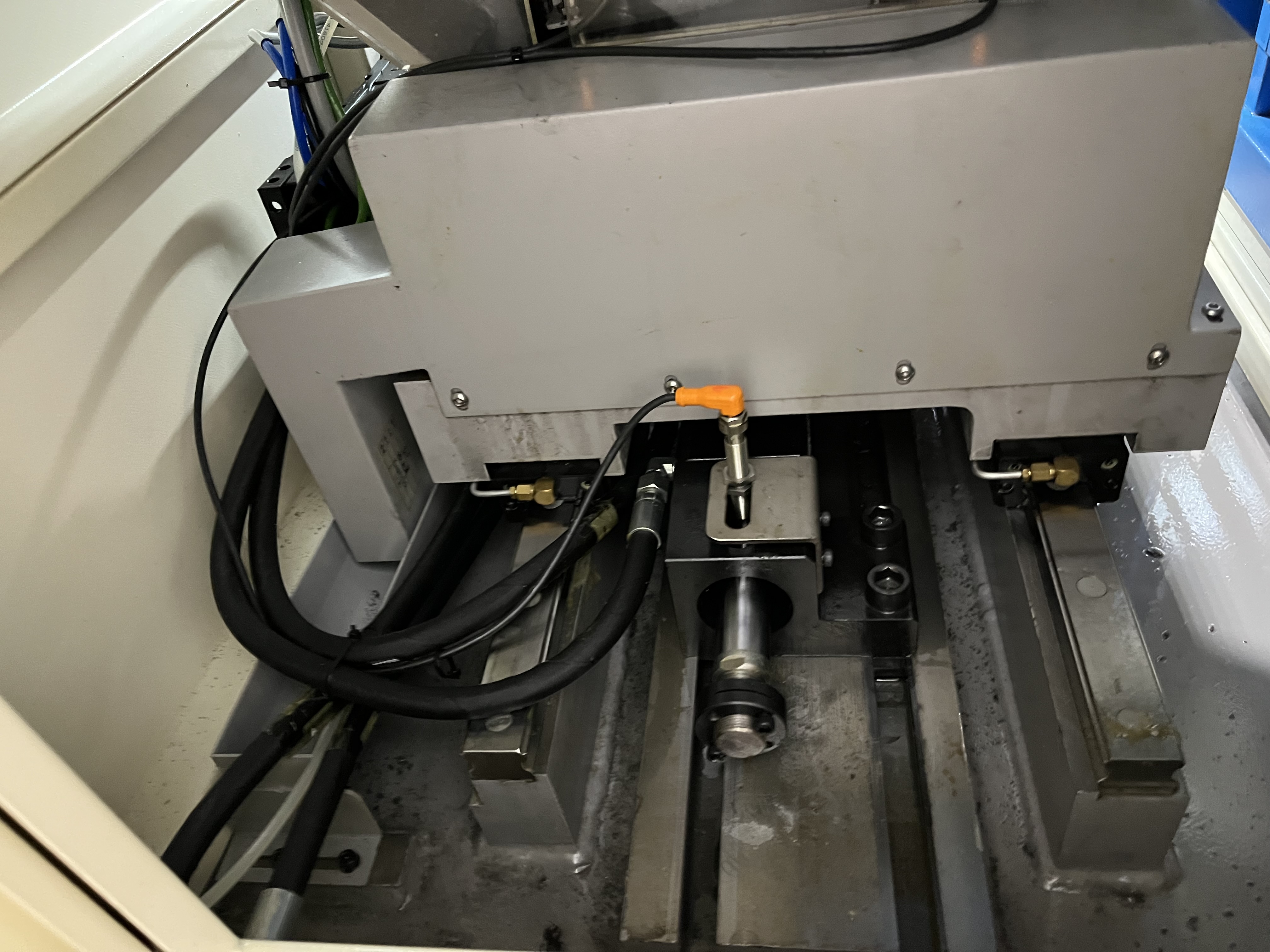
Piping design is where most coolant system installations go wrong. I have walked into shops with a $50,000 high-pressure pump and $300 worth of undersized pipe fittings that turned the whole investment into a 600 psi system instead of the designed 1,000 psi. The piping carries the coolant, but it also creates pressure losses that compound with every fitting, bend, and length of tube.
Pressure Drop Fundamentals
Every component in the coolant path adds resistance. The pressure drop through a system is proportional to the flow rate squared. Doubling the flow quadruples the pressure loss through the piping. This matters enormously in deep hole drilling because the flow rates are high and the pressure requirements are tight.
| Component | Pressure Drop per Unit (at 40 L/min, water) |
|---|---|
| 1 m of 1-inch schedule 40 pipe | 0.15 psi |
| 1 m of 3/4-inch schedule 40 pipe | 0.50 psi |
| Standard 90° elbow, 1-inch | 0.40 psi (equivalent to 2.7 m of pipe) |
| Long-radius 90° elbow, 1-inch | 0.25 psi (equivalent to 1.7 m of pipe) |
| Gate valve (fully open), 1-inch | 0.10 psi |
| Ball valve (fully open), 1-inch | 0.08 psi |
| Check valve, 1-inch | 0.60–1.20 psi |
I measured the pressure drop on a machine that had been converted from a 600 psi to a 1,200 psi pump without changing the piping. The existing 3/4-inch piping was creating 180 psi of pressure loss between the pump and the spindle inlet. The machine was delivering only 820 psi at the tool despite the new pump’s rated capacity.
Material Selection
Steel Pipe
Black steel or galvanized pipe is the traditional choice. It handles high pressure well but corrodes over time in water-based coolant. I do not use galvanized pipe in closed-loop coolant systems because the zinc coating flakes off and the particles damage seals. Black steel with a phosphate treatment is acceptable for pressures above 500 psi.
Stainless Steel
For high-pressure coolant systems, 304 or 316 stainless steel is my standard specification. It does not corrode, it handles 1,500 psi with standard wall thickness, and the smooth bore reduces pressure drop compared to steel pipe of the same nominal diameter. The material cost is roughly 2.5 to 4 times black steel, but the installation lasts the life of the machine.
| Material | Max Working Pressure (1-inch Sch 40) | Corrosion Resistance | Relative Cost |
|---|---|---|---|
| Black steel | 1,200 psi | Poor in water-based coolant | 1.0x |
| Galvanized steel | 1,200 psi | Fair (coating flakes) | 1.3x |
| 304 stainless | 1,500 psi | Excellent | 2.5x |
| 316 stainless | 1,500 psi | Excellent (better for chlorides) | 3.5x |
| Hydraulic hose | 2,000–5,000 psi | Good (replaceable) | 2.0–4.0x (per m) |
Hydraulic Hose
For machine axes that move or for connections subject to vibration, hydraulic hose is necessary. I use wire-braid reinforced hose with a minimum burst pressure of 4,000 psi for high-pressure systems. The hose bends create less pressure drop than steel elbows because the radius can be larger. I replace coolant hoses every two years regardless of visible condition because the inner liner degrades over time.
Pipe Sizing Rules
The most common mistake is undersizing the piping. I use a design velocity of 8 to 12 feet per second in pressure lines and 4 to 6 feet per second in suction lines. Higher velocities increase pressure drop and erosion. Lower velocities allow particles to settle.
| Line Size | Max Flow at 10 ft/s | Typical Application |
|---|---|---|
| 1/2 inch | 6 GPM (23 L/min) | Small gun drill return lines |
| 3/4 inch | 14 GPM (53 L/min) | Machine drop lines |
| 1 inch | 26 GPM (98 L/min) | Main supply to single spindle |
| 1.5 inch | 60 GPM (227 L/min) | Main supply to multiple spindles |
| 2 inch | 110 GPM (416 L/min) | Central system header |
| 3 inch | 260 GPM (984 L/min) | Main return line, central system |
I once audited a system where a 3-inch return line was carrying 350 GPM of coolant. The velocity was nearly 15 ft/s, and the pipe had eroded through the wall at three elbows within two years. Upsizing to a 4-inch return line fixed the problem.
Layout Best Practices
Keep the pump suction line as short as possible. Every foot of suction line adds resistance that the pump must overcome. I prefer to mount the pump directly on top of the coolant tank or as close as possible with a maximum 2-meter suction line. The suction line diameter should be one or two sizes larger than the pressure line diameter to reduce inlet restriction.
Use long-radius elbows wherever possible. Each standard 90-degree elbow is equivalent to 2 to 3 meters of straight pipe in pressure drop. Long-radius elbows reduce this to 1.5 to 2 meters. For high-pressure systems above 500 psi, I use only long-radius elbows or fabricated bends.
Install a bypass loop at the pump discharge with a pressure relief valve set at 10% above the maximum working pressure. This protects the system if a tool clogs or the flow path blocks. The return from the relief valve should go back to the tank, not to the suction line.
Integration with Filtration and Temperature Control
The piping layout must consider the coolant filtration maintenance and temperature control systems as part of the overall flow path. I put the filter housing downstream of the pump but upstream of any branches. This ensures all coolant is filtered before reaching the machine spindles. The heat exchanger goes between the filter and the machine header so that filtered, temperature-controlled coolant reaches every spindle.
Key Takeaways
- Pressure drop through piping can consume 15–25% of pump capacity if piping is undersized.
- Design for 8–12 ft/s velocity in pressure lines and 4–6 ft/s in suction lines.
- Stainless steel piping is worth the premium for corrosion resistance and service life.
- Long-radius elbows reduce pressure drop significantly compared to standard elbows.
- Keep suction lines under 2 meters and use one to two sizes larger than pressure lines.
- Bypass loop with relief valve protects the system from tool clog events.