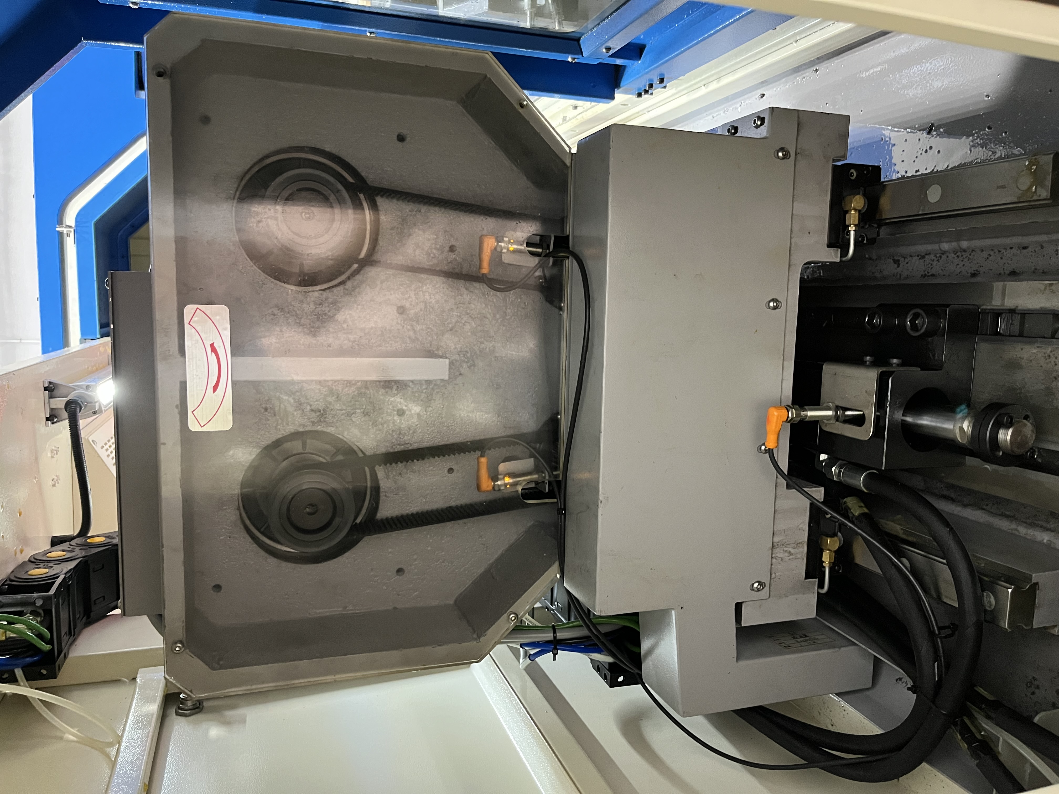
A deep hole drilling machine is a significant capital investment — often $200,000 to $1 million depending on size and capability. The acceptance test is your only opportunity to verify the machine meets specifications before you are committed to it.
I have been involved in several machine acceptance tests. Here is the procedure I use.
Documentation Review
Before any physical testing, I review the documentation:
- Machine specifications vs purchase order — confirm all options and features are present
- Electrical and hydraulic schematics
- Operator and maintenance manuals
- Spindle runout certificate from the manufacturer
- Coolant pump performance curve
- Alignment certificate from the manufacturer
If any documentation is missing, I note it on the acceptance report. Missing manuals will cause problems later.
Spindle Runout Test
The spindle is the heart of the machine. I measure runout at two locations:
| Measurement Point | Acceptable | Marginal | Reject |
|---|---|---|---|
| Spindle taper (test bar at nose) | Under 0.005mm | 0.005-0.008mm | Over 0.008mm |
| Test bar at 200mm from nose | Under 0.010mm | 0.010-0.015mm | Over 0.015mm |
I use a dial indicator with 0.001mm resolution. A 0.01mm indicator is not accurate enough for this test.
If the spindle runout exceeds the reject limits, I do not proceed with further testing until the manufacturer corrects it.
I cover runout measurement in Gun Drill Runout Effects.
Guide Bushing Holder Concentricity
The guide bushing holder must be concentric with the spindle axis. I check this by mounting an indicator on the spindle and sweeping the bushing holder bore.
| Measurement | Acceptable | Marginal | Reject |
|---|---|---|---|
| Bushing holder TIR | Under 0.015mm | 0.015-0.025mm | Over 0.025mm |
If the holder is adjustable, I adjust it. If it is fixed, I document the reading and require correction.
Axis Alignment
The spindle axis must be parallel to the way axis in both horizontal and vertical planes.
| Check Direction | Acceptable per Meter | Marginal per Meter |
|---|---|---|
| Horizontal (X axis) | Under 0.010mm/m | 0.010-0.015mm/m |
| Vertical (Y axis) | Under 0.010mm/m | 0.010-0.015mm/m |
I check this using a test bar in the spindle and an indicator mounted on the carriage, running the carriage along the ways while indicating on the bar.
I cover alignment in Machine Alignment and Concentricity.
Coolant System Performance
The coolant system is the most common source of problems on new deep hole drilling machines.
| Test | Acceptance Criteria |
|---|---|
| Maximum pressure at pump | Per manufacturer spec (±5%) |
| Maximum pressure at tool holder | At least 80% of pump pressure |
| Flow rate at tool holder | Per manufacturer spec (±10%) |
| Coolant temperature stability | Within 5°C after 1 hour of operation |
| Filtration system | No visible particles in return coolant |
| Rotary union leak | No visible leakage at operating pressure |
I run the coolant system for one hour at maximum pressure and check for leaks, pressure drop, and temperature rise.
Test Cut
The final and most important test: drill a test hole in a standard material and verify the results.
I use 4140 steel at 25-30 HRC for the test cut. The test hole should be at the machine’s typical operating diameter and at least 30:1 L/D ratio.
| Test Result | Acceptance Criteria |
|---|---|
| Diameter tolerance | Within IT8 |
| Surface finish | Ra 0.8μm or better |
| Straightness | 0.2mm/m or better |
| Cycle time | Within 10% of manufacturer estimate |
If the test cut does not meet these criteria, I investigate whether the issue is the machine, the tooling, or the parameters before rejecting.
Documentation to Keep
After acceptance, I keep the following on file:
- Signed acceptance report with all measurements
- Spindle runout certificate
- Alignment data
- Coolant system test results
- Test cut data and inspection report
- Photographs of the machine and installation
This documentation serves as a baseline for future maintenance. If spindle runout increases over time, I compare the current reading to the acceptance test data to determine the rate of wear.
Key Takeaways
- Measure spindle runout at two locations before anything else. If it fails, stop the acceptance test.
- Check guide bushing holder concentricity to within 0.015mm TIR. Misalignment here causes every hole to drift.
- Verify spindle axis to way parallelism within 0.010mm/m in both planes.
- Run the coolant system at full pressure for one hour. Check for leaks, pressure drop, and temperature rise.
- Drill a test cut in 4140 steel at typical operating parameters. Verify diameter, finish, and straightness.
- Keep all acceptance test data as a baseline for future maintenance comparisons.