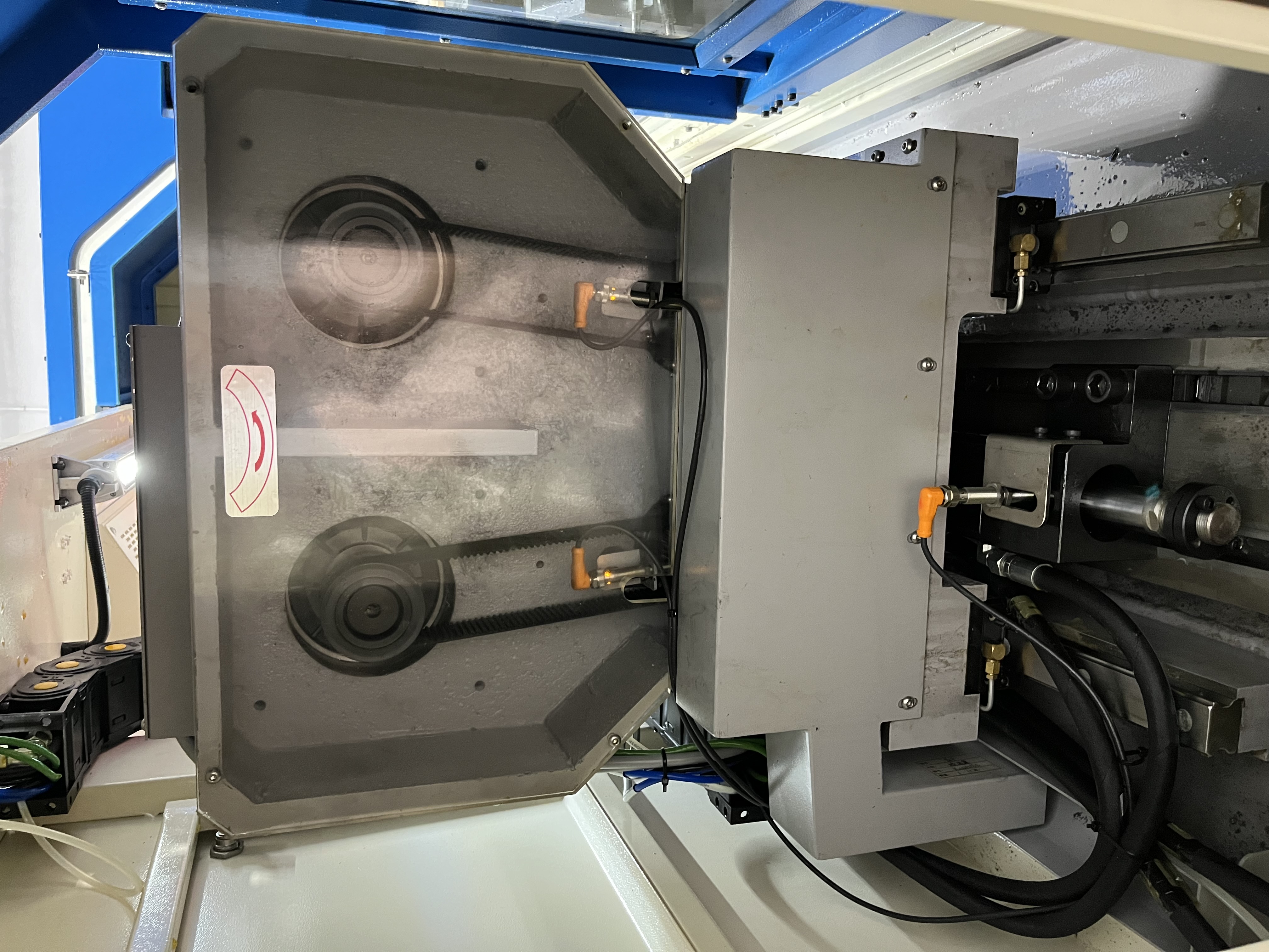
Integrating in-process gauging with the machine control allows automatic measurement of the bore diameter during the drilling cycle. The gauge measures the bore immediately after drilling and the control records the data, adjusts parameters, or alerts the operator. I have implemented these systems on several production machines and the improvement in quality consistency has been substantial.
System Architecture and Components
The in-process gauging system consists of a measuring probe, a data interface, and the CNC control integration. The measuring probe can be an air plug or a contact probe mounted near the spindle or on a separate slide.
| Component | Function | Air Gauge Type | Contact Probe Type |
|---|---|---|---|
| Measuring probe | Measures bore diameter | Air plug with orifices | LVDT or linear scale contact fingers |
| Signal conditioner | Converts sensor signal to data | Pneumatic-to-electric converter | Amplifier and A/D converter |
| Data interface | Communicates with CNC | RS-232, Ethernet, or analog | RS-232, Ethernet, or analog |
| CNC integration | Displays data, triggers actions | Custom macro or HMI screen | Custom macro or HMI screen |
| SPC software (optional) | Tracks trends | Database with charting | Database with charting |
The system works with an air plug or contact probe mounted near the spindle. After the drill retracts, the gauge advances into the bore and measures the diameter. The reading goes to the CNC control through a data interface.
Air gauges are the most common choice for deep hole drilling because they are non-contact and tolerate coolant contamination. The air plug has two or more orifices that direct air jets at the bore surface. The back pressure in the air supply changes with the gap between the plug and the bore surface. The back pressure is calibrated to the bore diameter.
I prefer contact probes for bores under 6mm diameter where air gauges are less accurate. The contact probe has two fingers that contact the bore surface and transmit the displacement to a linear scale or LVDT. Contact probes are more accurate than air gauges on small bores but are more sensitive to coolant and chips.
Data Integration and Control Response
The main benefit of in-process gauging is immediate feedback. If the diameter trends upward over several parts, the control can signal the operator to change the tool before the parts go out of spec. I have programmed the control to display a warning message when the diameter approaches the upper tolerance limit.
| Measurement Result | Control Action | Operator Response |
|---|---|---|
| Within 50% of tolerance | No action, log data | Continue production |
| Between 50% and 75% of tolerance | Display caution message | Monitor more frequently |
| Between 75% and 100% of tolerance | Display warning, flash light | Prepare tool change |
| Exceeds tolerance | Stop machine, display alarm | Inspect tool and adjust |
I have used in-process gauging on production jobs where the bore tolerance was plus or minus 0.025mm. The system caught a gradual diameter increase caused by tool wear and alerted the operator at the right time to change the tool. Without the system, the operator would have continued running until a part failed inspection — which might take hours if the parts are not inspected immediately.
The gauge data can also be used for automatic tool offset adjustment. If the bore is trending toward the high side, the control can apply a small tool offset to bring the diameter back to center. I have implemented this on a few machines with good results, but I use it cautiously because automatic offset changes can mask developing problems.
SPC Integration and Trend Analysis
The gauge data can be fed into an SPC system for trend analysis. I track the diameter readings in a control chart and review the trends weekly. The trends tell me when the process is stable and when adjustments are needed.
| SPC Metric | Target Value | Action When Triggered |
|---|---|---|
| Process capability (Cpk) | Above 1.33 | No action needed |
| Process capability (Cpk) | 1.00 - 1.33 | Review process, plan improvements |
| Process capability (Cpk) | Below 1.00 | Stop production, investigate |
| Run of 7 points above centerline | N/A | Check tool wear, adjust parameters |
| Run of 7 points trending up | N/A | Check tool wear, monitor closely |
| Point outside control limits | N/A | Stop and investigate immediately |
I set up the SPC system to track the bore diameter, the surface finish, and the coolant pressure as key process indicators. The three parameters together provide a good picture of the process health. A change in any one parameter without a change in the others indicates a specific type of problem.
The SPC data is reviewed weekly in a production meeting. The operators, the quality inspector, and the production manager review the charts and discuss any trends. The meetings have been effective at identifying chronic problems that no one noticed during the daily rush.
System Payback and Cost Justification
The in-process gauging system cost is about $5,000 to $15,000 depending on the accuracy and features. For high-production jobs with tight tolerances, the system pays for itself by preventing scrap.
I calculated the payback on a job running 50,000 parts per year with a bore tolerance of plus or minus 0.025mm. The scrap rate before the gauging system was 3 percent. After installing the system, the scrap rate dropped to 0.5 percent. The scrap savings of 1,250 parts per year at $15 per part saved $18,750 annually, paying for the $10,000 system in about 7 months.
The system also reduces the inspection labor cost. Before the gauging system, the operator stopped every 10th part and measured it with a bore gauge. The measurement took about 2 minutes per part, which added 10 minutes per 100 parts to the cycle time. The gauging system measures every part automatically and eliminates the manual inspection time.
Calibration and Maintenance
The gauging system must be calibrated regularly to maintain accuracy. I calibrate air gauges weekly using a master ring gauge that is traceable to NIST standards. The calibration takes about 15 minutes and ensures the measurement accuracy is within plus or minus 0.002mm.
Contact probes need more frequent calibration because the contact fingers wear from repeated contact with the bore surface. I calibrate contact probes at the start of every shift and replace the contact fingers when the wear exceeds 0.01mm. The finger replacement takes about 10 minutes and costs $50 to $100 per set.
Key Takeaways
- In-process gauging systems using air plugs or contact probes measure the bore diameter automatically after each drilling cycle, providing immediate feedback on process stability.
- The system alerts the operator when the diameter approaches 75 percent of the tolerance limit, allowing a tool change before producing out-of-spec parts.
- SPC integration with control chart monitoring of Cpk values — target above 1.33, investigate below 1.00 — provides weekly trend analysis for process improvement.
- On a 50,000-part job with plus or minus 0.025mm tolerance, the gauging system reduced scrap from 3 percent to 0.5 percent, saving $18,750 per year and paying for the $10,000 system in 7 months.
- Automatic tool offset adjustment is possible but I use it cautiously because it can mask developing tool wear problems.
- I recommend in-process gauging for any production job with a bore tolerance tighter than plus or minus 0.05mm and a production volume over 1,000 parts per year.