A laser interferometer measures machine positioning accuracy with sub-micron resolution. I use one for annual calibration of production deep hole drilling machines. The first time I ran a full laser calibration on a machine that was supposedly within spec, I found positioning errors of 0.08 mm per meter — four times the acceptable limit. The compensation corrected those errors and improved the hole position repeatability from 0.05 mm to 0.01 mm.
How the System Works
The laser head mounts on a tripod and the reflector mounts on the machine spindle. As the machine moves, the laser measures the actual position and compares it to the commanded position. The difference is the positioning error. The laser operates by splitting a beam into two paths — one reflects off a stationary reference mirror and the other off a moving reflector on the machine. The interference pattern between the two beams changes as the machine moves, and counting the fringe changes gives the displacement.
The resolution of a modern laser interferometer is 1 nanometer (0.001 micron). In practice, environmental factors limit the effective resolution to about 0.1 micron. Air temperature, pressure, and humidity all affect the speed of light and must be compensated for. The laser system includes an environmental compensation unit that measures these parameters and applies a correction factor. I always let the system warm up for at least 30 minutes before taking measurements to allow the laser tube temperature to stabilize.
| Component | Purpose | Mounting Location |
|---|---|---|
| Laser head | Generates the laser beam and receives the return signal | Tripod on floor, aligned with machine axis |
| Linear reflector | Reflects the beam back to the laser head | Machine spindle or tool holder |
| Environmental compensation unit | Measures air temperature, pressure, humidity | Near the measurement path |
| Tripod and optics mount | Provides stable platform for laser head | Floor, isolated from machine vibration |
| PC with software | Records data and generates compensation tables | Operator station or cart |
Measurements the Interferometer Provides
The interferometer measures linear positioning accuracy, straightness of travel, pitch and yaw, and squareness between axes. For a deep hole drilling machine, the most important measurements are linear accuracy and straightness of the drilling axis. I run the full suite of measurements annually, but the linear and straightness measurements get extra attention because they directly affect hole position and straightness.
Linear positioning accuracy measures how close the actual position is to the commanded position at points along the axis travel. The ISO 230-2 standard defines the measurement procedure and the calculation of the positioning accuracy value. I measure at 10 mm intervals over the full travel, then in reverse at the same points to measure backlash and hysteresis.
Straightness of travel measures how much the machine axis deviates from a straight line as it moves. This measurement is critical for deep hole drilling because a machine with poor straightness produces curved holes. I measure straightness in both the horizontal and vertical planes for the drilling axis.
| Measurement Type | What It Detects | Tolerance for Deep Hole Drilling |
|---|---|---|
| Linear positioning accuracy | Ball screw wear, encoder errors | +/- 0.01 mm per meter |
| Bidirectional repeatability | Backlash in ball screw or gearbox | 0.005 mm |
| Straightness of travel (horizontal) | Way wear, misalignment | 0.01 mm per meter |
| Straightness of travel (vertical) | Way wear, head sag | 0.01 mm per meter |
| Pitch | Leveling errors, way wear | 10 arc-seconds per meter |
| Yaw | Side-to-side guide way wear | 10 arc-seconds per meter |
| Squareness between axes | Column or base alignment | 0.01 mm per 300 mm |
Running the Calibration Program
I run the calibration program at several feed rates to check for speed-dependent errors. A ball screw with pitch error shows up as a periodic error pattern with the period equal to the screw lead. Worn guide ways show up as increasing error at the ends of travel where the ways see the most wear from oil starvation during acceleration and deceleration.
The measurement procedure follows a standard cycle: position the axis at the start point, record the laser reading, command the axis to move to the next point, wait 2 seconds for the position to settle, record the reading, and repeat. The wait time is important because the axis overshoots the commanded position and needs time to settle to its final position. A machine with high inertia or poor servo tuning may need 3-5 seconds to settle.
I run the measurements at 50% and 100% of the normal feed rate to isolate speed-dependent effects. A ball screw with a bent section shows more error at higher speeds because the nut traverses the bent section faster and the centrifugal force increases the deflection. Worn ball screw preload shows up as increasing error at higher speeds because the screw whips more.
| Feed Rate | Error Pattern | Likely Cause |
|---|---|---|
| 50% of normal | Periodic error at screw lead pitch | Ball screw pitch error |
| 100% of normal | Same pattern as 50%, same magnitude | No speed-dependent issue |
| 100% of normal | Larger error than 50% | Speed-dependent issue: bent screw or worn preload |
| All feed rates | Error increases at travel ends | Way wear at travel extremes |
Entering Compensation into the CNC
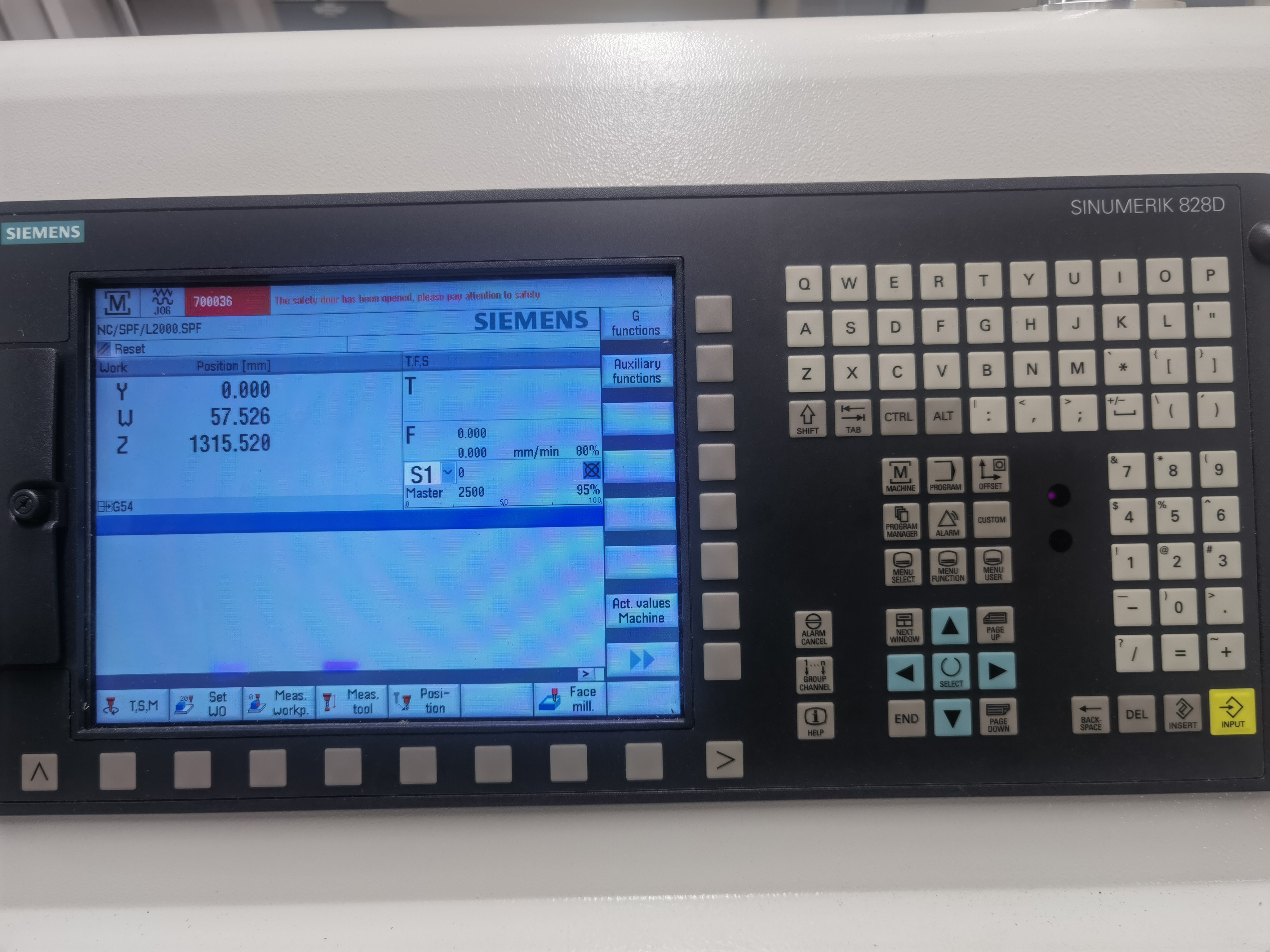
The calibration data can be entered into the CNC control as compensation values. Most modern controls accept linear and angular compensation tables. The Fanuc, Siemens, and Heidenhain controls I have worked with all accept compensation tables in different formats, but the principle is the same — the control applies a correction to the commanded position based on the measured error at each point along the travel.
The compensation table is typically an array of error values at fixed intervals along each axis. The control interpolates between the compensation points to calculate the correction for any commanded position. The interval between compensation points should be equal to or less than the pitch of the ball screw to capture the periodic error pattern. I use 10 mm intervals for machines with 10 mm lead ball screws and 20 mm intervals for machines with 20 mm lead ball screws.
After entering the compensation values, I run a verification measurement to confirm the compensation is correct. The verification should show positioning errors reduced to within the machine specification. If the errors are still out of tolerance, the mechanical condition of the machine needs attention before compensation can correct it. No amount of compensation fixes a machine with worn out guide ways or loose ball screw bearings.
| Control Brand | Compensation Table Type | Maximum Compensation Points |
|---|---|---|
| Fanuc Series 30i/31i | Pitch error compensation | 128 points per axis |
| Siemens 840D sl | Sag compensation table | 100 points per axis |
| Heidenhain iTNC 530 | Linear compensation table | 200 points per axis |
Calibration Schedule and Practical Considerations
I calibrate annually or after any major machine repair. A machine that is out of calibration by 0.02 mm per meter produces holes that are off-position by that amount over the hole length. For a 500 mm deep hole, that is 0.01 mm of position error at the bottom of the hole. The laser calibration finds these errors and the compensation corrects them.
The annual calibration schedule is tied to the machine’s preventive maintenance schedule. I calibrate the machine immediately after completing the mechanical maintenance — adjusting gibs, replacing wiper seals, and checking ball screw preload. Calibrating a machine that is due for mechanical maintenance wastes time because the compensation values will change after the maintenance is done.
The laser system cost is about $15,000-25,000. I hire a calibration service for the annual check instead of buying the system. The calibration service costs $1,500-2,500 per machine per year including a detailed report. At that rate, buying the system only makes sense if I am calibrating more than 10 machines per year. For my shop with 6 machines, hiring the service is the better economic choice.
The environmental conditions during the calibration affect the results. I schedule the calibration for early morning when the shop temperature is most stable. A temperature change of 1 C during the measurement causes a thermal expansion error of 0.011 mm per meter of steel. Running the calibration when the temperature is stable eliminates this source of error.
Key Takeaways
- Laser interferometer calibration measures linear positioning, straightness, pitch, yaw, and squareness with sub-micron resolution.
- Run measurements at multiple feed rates to isolate speed-dependent errors from geometry errors.
- Use 10-20 mm compensation intervals matched to the ball screw lead for effective error correction.
- Calibrate annually after completing mechanical maintenance — never before.
- Hire a calibration service at $1,500-2,500 per machine per year unless you have more than 10 machines.
- Schedule calibration during stable thermal conditions, preferably early morning when shop temperature is constant.
- Verify compensation with a post-correction measurement to confirm the errors are within spec.