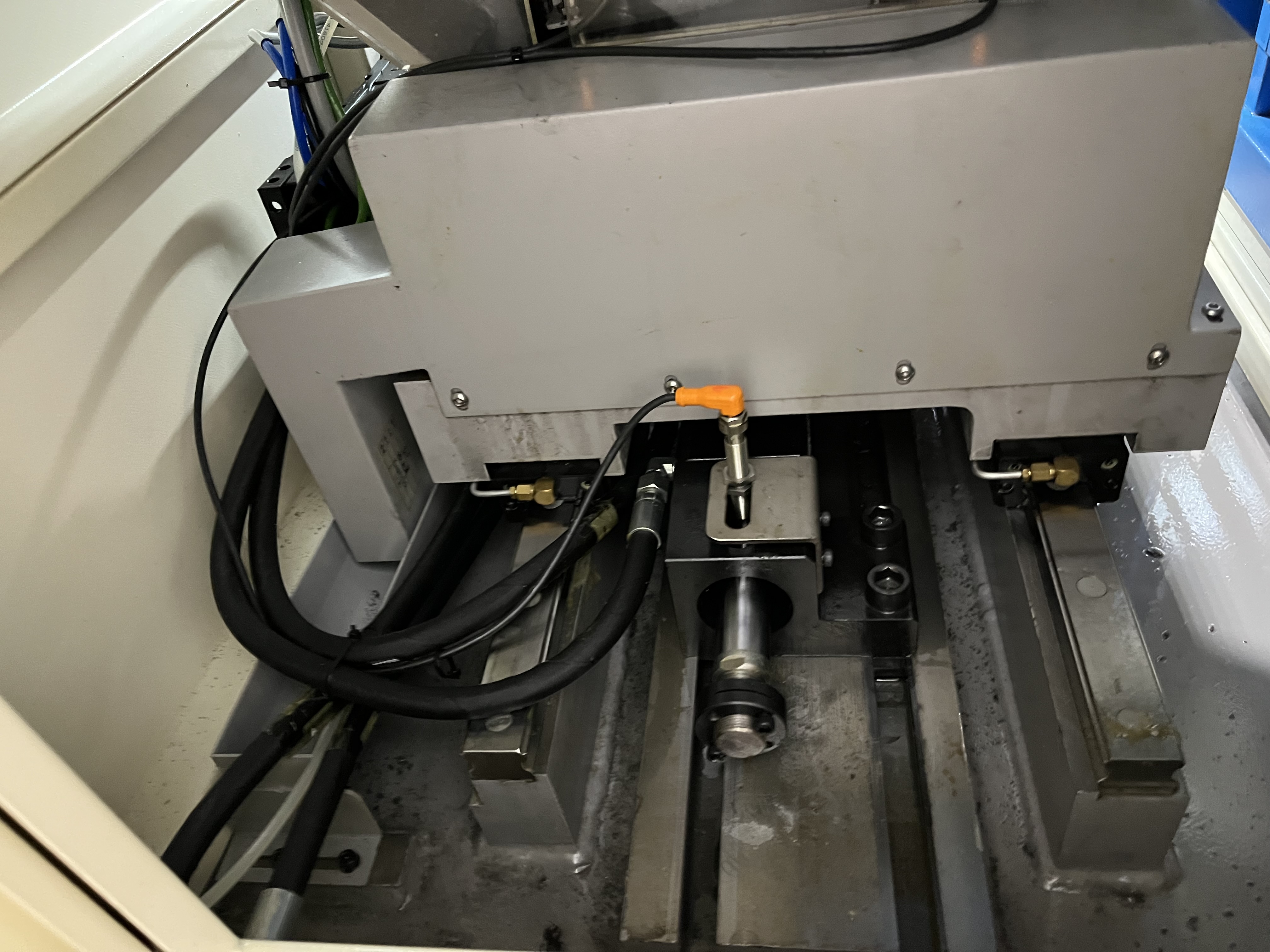
The electrical system on a deep hole drilling machine includes the main power supply, CNC control, servo drives, coolant pump motor, and safety circuits. I have dealt with electrical failures on dozens of machines over the years, and the most expensive lessons have been about preventing problems before they cause downtime. A well-maintained electrical system is the foundation of reliable production.
Main Electrical System Architecture
The electrical system on a typical deep hole drilling machine follows a standard architecture with variations based on the machine size and control type. I have mapped out the key components and their power consumption based on machines I have worked with.
| Component | Typical Power Rating | Voltage | Common Failure Mode | Mean Time Between Failures | Replacement Cost |
|---|---|---|---|---|---|
| Main disconnect / breaker | 100 - 400 A | 480 VAC 3-phase | Welded contacts | 10+ years | $500 - $2000 |
| CNC control unit | 500 - 2000 W | 24 VDC / 120 VAC | Power supply failure | 5 - 8 years | $8000 - $15000 |
| Servo drives (per axis) | 2 - 10 kW | 480 VAC 3-phase | IGBT module failure | 3 - 6 years | $2000 - $5000 |
| Spindle drive | 10 - 50 kW | 480 VAC 3-phase | Capacitor bank failure | 5 - 7 years | $5000 - $12000 |
| Coolant pump motor starter | 5 - 30 kW | 480 VAC 3-phase | Contactor welding | 2 - 4 years | $500 - $2000 |
| Coolant pump VFD | 5 - 30 kW | 480 VAC 3-phase | Cooling fan failure | 3 - 5 years | $2000 - $6000 |
| Safety relay module | 10 - 50 W | 24 VDC | Internal relay failure | 5 - 8 years | $800 - $2500 |
| Transformers | 1 - 50 kVA | 480 VAC / 120 VAC | Overheating | 10+ years | $1000 - $4000 |
The main power supply feeds through a disconnect switch and fuses or a circuit breaker to the control transformer. The transformer steps down 480 VAC to 120 VAC for the control circuits and to 24 VDC for the CNC and I/O. I check the transformer output voltage annually. A transformer that is outputting low voltage causes intermittent control problems that are hard to diagnose.
Electrical Maintenance Schedule
I follow a scheduled maintenance plan for the electrical system. The schedule is tied to operating hours rather than calendar time, but I use calendar intervals when the machine runs inconsistently:
| Component | Daily | Weekly | Monthly | Quarterly | Annually |
|---|---|---|---|---|---|
| Main disconnect | Visual check | — | — | — | Thermal scan |
| CNC control unit | Check for alarm codes | Clean air filter | — | Battery backup test | Full diagnostic |
| Servo drives | — | — | Check fan operation | Clean heat sinks | Check bus capacitors |
| Spindle drive | — | — | Check fan operation | Clean heat sinks | Replace air filters |
| Coolant pump VFD | — | — | Check display for faults | Verify motor current | Thermal scan, clean cooling fan |
| Safety relays | Test E-stop weekly | — | — | — | Functional test all circuits |
| Control transformer | — | — | — | Check output voltage | Thermal scan |
| Cabinet purge fan | — | Check filter | — | Clean or replace filter | Replace fan if noisy |
| Ground connection | — | — | — | — | Measure ground resistance |
| All connections | — | — | — | — | Torque check, thermal scan |
I keep a maintenance log with the date, hours, and findings for each task. The log has saved me multiple times — when a drive fails, I check the log to see when the cooling fan was last cleaned and whether the drive had been running hot.
Coolant Contamination in Electrical Enclosures
The most common electrical problem I see on deep hole drilling machines is coolant contamination. Coolant mist gets into electrical enclosures through seal gaps around conduit entries, door gaskets, and component vents. The coolant conducts electricity and causes shorts between terminals.
I have found coolant inside electrical cabinets more times than I can count. The coolant mist condenses on the inside of the cabinet door and drips onto terminal strips and drives. The first sign is usually an intermittent fault that the operator clears by cycling power. Over time, the short becomes permanent and a drive or power supply fails.
I keep the electrical cabinet sealed by checking the door gaskets for damage every month. I also add a small cabinet purge fan with a filter that maintains positive pressure inside the cabinet. The positive pressure prevents coolant mist from being drawn in through seal gaps. On machines running oil-based coolants, I also install a cabinet heater that maintains the internal temperature above the dew point to prevent condensation.
The conduit entries need to be sealed with conduit plugs or sealing washers. I have found gaps around conduit entries where coolant drips down the outside of the conduit and runs into the cabinet. Sealing these gaps with silicone or rubber grommets stops the problem.
Loose Connections and Intermittent Faults
Loose connections cause intermittent problems that are the hardest to diagnose. A loose terminal on a servo drive can cause random axis faults that come and go without warning. The fault appears when the machine vibrates at a specific frequency that makes the loose connection break contact.
I check all critical connections during annual maintenance. I use a thermal imaging camera to scan the electrical cabinet while the machine is running. A loose connection shows up as a hot spot because of increased resistance. I have found loose main power connections, loose drive bus bars, and loose transformer connections using thermal imaging that I would never have found by visual inspection.
The torque specification for power connections matters. I use a torque screwdriver on all power terminals and follow the manufacturer specifications. Undertorqued connections loosen over time from thermal cycling. Overtorqued connections damage the terminal strip and cause high resistance.
I also check the connection between the machine frame and the building ground. A poor ground connection causes noise on the control signals and can cause random axis position errors. I measure the ground resistance annually and keep it under 1 ohm. A high ground resistance is often the root cause of unexplained position errors and servo faults that I have seen operators attribute to the CNC control.
Common Faults and Diagnosis
Here is a diagnosis table for the most common electrical faults I encounter on deep hole drilling machines:
| Symptom | Likely Cause | How to Verify | Fix | Typical Downtime |
|---|---|---|---|---|
| Machine dead — no power | Main breaker tripped or disconnect open | Check voltage at disconnect output | Reset breaker, investigate cause | 10 min |
| CNC screen blank but fans running | 24 VDC power supply failed | Measure DC output voltage | Replace power supply module | 1 - 2 hours |
| Spindle won’t start | Safety relay not energized | Check E-stop chain continuity | Reset E-stop, check door interlock | 15 min |
| Random servo fault on Z-axis | Loose connection on drive | Thermal scan of drive terminals | Tighten connections to spec torque | 1 hour |
| Coolant pump runs but low pressure | VFD fault or phase loss | Check VFD display for error code, measure output voltage | Clear fault or replace VFD module | 2 - 4 hours |
| Axis position drifting | Encoder signal noise from poor ground | Measure ground resistance | Improve ground connection | 4 hours |
| Intermittent tool change fault | Limit switch damaged from coolant contamination | Inspect switch for coolant ingress | Replace switch, seal enclosure | 1 hour |
| Spindle speed fluctuates | Encoder feedback issue or drive parameter corruption | Check encoder wiring, reload drive parameters | Replace encoder cable or reload parameters | 2 - 8 hours |
| Coolant pump motor hums but won’t start | Failed start capacitor or single-phasing | Measure voltage on all three phases | Replace capacitor or check contactor | 2 hours |
I keep a printed copy of this table in the electrical cabinet. When a new operator calls me with a fault, I can walk them through the diagnosis steps over the phone. About 80 percent of the electrical faults I see fall into one of these nine categories.
Safety Procedures
I follow a strict set of safety procedures when working on electrical systems. The risks on deep hole drilling machines are higher than typical machine tools because the coolant pump systems store hydraulic energy even when the machine is off.
- Lockout-tagout (LOTO) — I lock the main disconnect in the off position and tag it with my personal lock. I test for zero voltage at the drive DC bus before touching any components. The DC bus capacitors can hold a lethal charge for 5 to 10 minutes after power-off.
- Coolant system isolation — I close the coolant shut-off valve and bleed the pressure from the pump discharge line before opening the electrical cabinet. Coolant lines near electrical components create a shock hazard if the coolant is conductive.
- Personal protective equipment — I wear insulating gloves and safety glasses for any work inside the cabinet. Cat 2 arc flash rated gloves are minimum for 480 VAC work.
- One-hand rule — When measuring live circuits, I keep one hand in my pocket to prevent a path across my chest if I contact a live conductor.
- Verify meter function — I test the multimeter on a known live source before and after testing the circuit. A meter with a dead battery gives a false zero reading.
- Clean-up — I remove all tools, wire clippings, and debris from the cabinet before closing the door. A stray wire clipping left in the cabinet can cause a short circuit when the machine vibrates.
I train every maintenance technician on these procedures before they work on any machine. The procedures have prevented injuries in my shop — the close calls I have had were all situations where someone skipped a step.
Coolant Pump Motor Failures
The coolant pump motor is a common failure point on deep hole drilling machines. The motor runs continuously during the drilling cycle and is exposed to coolant mist, heat, and vibration. I check the motor current draw monthly by measuring the current on each phase with a clamp meter.
An increase in current draw of 10 percent or more over the baseline reading indicates a problem. The most common causes are bearing wear, pump load increase from partial blockage, or motor winding degradation. I track the current readings in a log and schedule motor replacement when the trend shows a steady increase.
I have found that coolant pump motors fail more often when the coolant temperature is above 40 degrees Celsius. The heat degrades the motor winding insulation over time. Installing a coolant chiller that maintains the coolant below 30 degrees Celsius extends motor life significantly.
I keep a spare coolant pump motor in stock for each machine size. The motor is usually a standard NEMA frame size that costs $1,000 to $3,000. Having a spare on hand reduces downtime from a week to a few hours when a motor fails.
The coolant pump motor also interacts with the coolant chemistry — I have covered this in the coolant additives overview. Coolant with the wrong pH or excessive bacterial growth attacks the motor shaft seal and causes coolant to wick into the motor windings. I have replaced three pump motors on one machine because the coolant pH had dropped to 7.5 and the seals were leaking. Fixing the coolant chemistry solved the motor failure problem.
For the electrical system as a whole, the coolant pump drive represents the largest single electrical load on the machine. I have covered the energy implications of pump selection in the coolant energy comparison article — choosing a positive displacement pump over a centrifugal pump reduces the electrical load substantially.
Key Takeaways
- Coolant contamination in electrical enclosures is the most common electrical failure mode on deep hole drilling machines — positive pressure purge systems with filters prevent it.
- I use thermal imaging annually to find loose connections before they cause intermittent faults, with hot spots indicating increased resistance from loose terminals.
- I follow a scheduled maintenance plan with daily, weekly, monthly, quarterly, and annual tasks — the maintenance log helps diagnose drive failures by showing thermal history.
- Coolant pump motor current draw should be monitored monthly, with a 10 percent increase over baseline indicating wear or blockage.
- Ground resistance between the machine frame and building ground should be kept under 1 ohm to prevent control signal noise.
- About 80 percent of electrical faults fall into nine common categories — I keep a diagnosis table in the electrical cabinet for quick reference.
- I follow strict lockout-tagout procedures including testing for zero voltage at the DC bus, which can hold a lethal charge for 5-10 minutes after power-off.
- Maintain the coolant temperature below 30 degrees Celsius to extend pump motor insulation life.
- Coolant chemistry directly affects pump motor seal life — I have covered this in the coolant additives article.
- Keep spare fuses, contactors, a drive module, and a coolant pump motor in stock to reduce downtime from electrical failures.