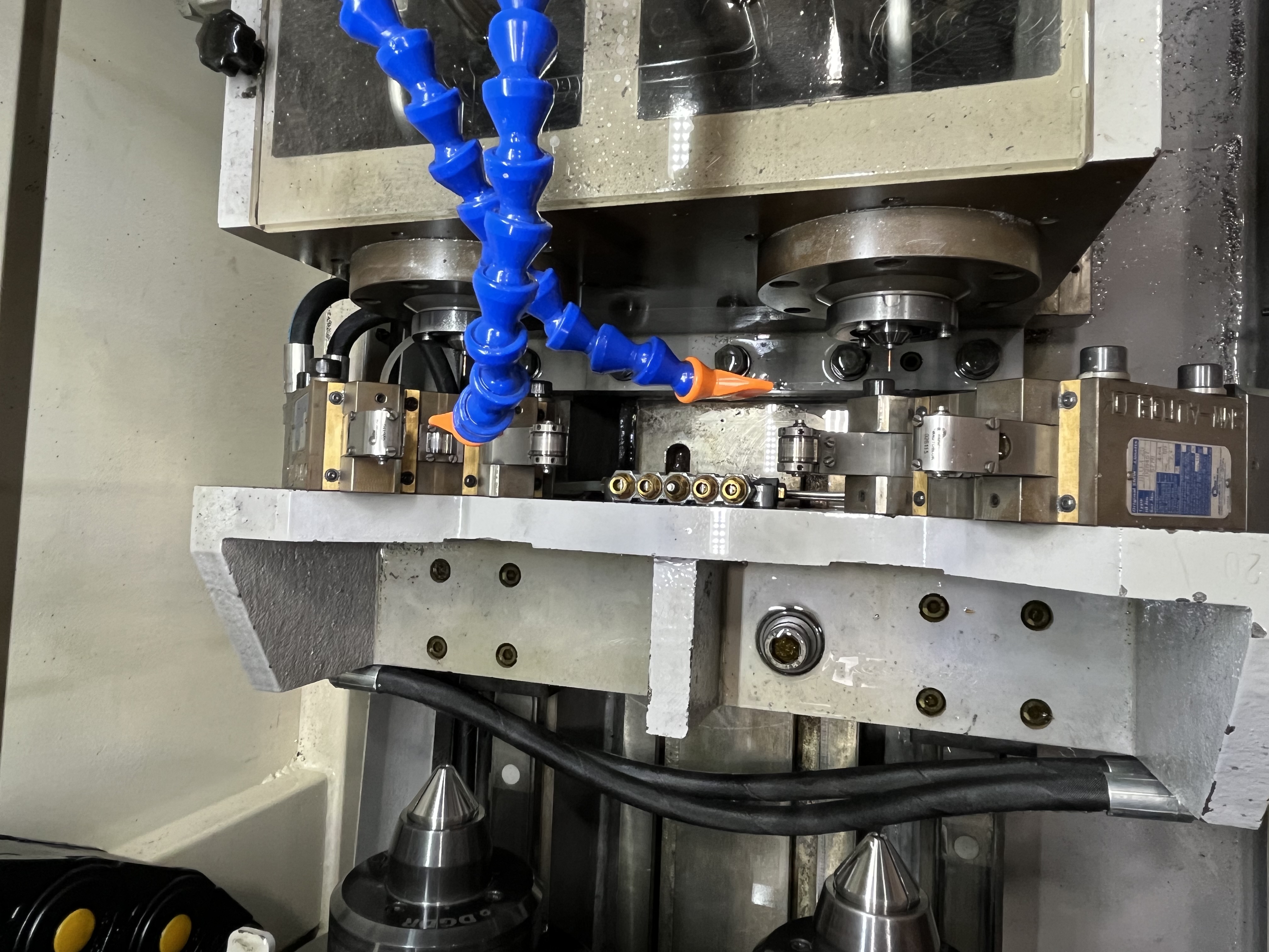
Machine vibration during deep hole drilling causes chatter marks on the bore surface and reduces tool life. I have traced most vibration problems to three root causes: foundation issues, worn bearings or drive components, and workpiece resonance. Each cause produces a different vibration pattern, and identifying the pattern is the first step toward a fix.
Vibration Diagnosis by Pattern
I have learned to recognize vibration patterns by observing the chatter marks on the bore surface and feeling the machine during operation. The following table summarizes the patterns I have encountered and their most likely causes.
| Vibration Pattern | Chatter Mark Spacing | Frequency Range | Most Likely Cause | Onset Pattern |
|---|---|---|---|---|
| Low rumble | Irregular, 5 - 20 mm apart | 10 - 50 Hz | Foundation looseness or resonance | Gradual or sudden |
| Regular chatter | Even, 1 - 5 mm apart | 50 - 200 Hz | Spindle bearing wear | Gradual increase |
| High-frequency squeal | Very fine, under 0.5 mm | 200 - 1000 Hz | Tool resonance or whip | Sudden at depth |
| Irregular thumping | Random spacing | Variable | Loose component or chip packing | Sudden onset |
| Mid-range harmonic | Consistent 2 - 8 mm | 50 - 150 Hz | Workpiece resonance | Specific speed range |
| Torsional chatter | Helical marks on bore | 30 - 80 Hz | Drive train wind-up or belt slip | Load-dependent |
I start troubleshooting by asking the operator whether the vibration started suddenly or gradually. Sudden onset points to a loose component, a broken weld on the machine base, or a chip packing problem in the bore. Gradual increase over weeks or months points to bearing wear or a foundation settling issue.
I also ask whether the vibration changes with spindle speed. If the vibration appears only at certain speeds, workpiece resonance is the likely cause. If the vibration is present at all speeds, the problem is in the machine structure or foundation.
For a more systematic approach to machine verification, I use a test bar procedure to separate alignment issues from dynamic vibration sources. The test bar tells me whether the spindle axis is straight — if it is, the vibration is coming from dynamics rather than geometry.
Foundation Issues
Foundation issues are the easiest to fix and the most commonly overlooked cause of vibration. Loose foundation bolts or missing leveling shims allow the machine to vibrate against the floor. I check foundation bolt torque quarterly and re-level the machine if needed.
The foundation for a deep hole drilling machine should be a reinforced concrete slab that is independent of the building floor. I have seen machines installed directly on the shop floor without any foundation prep, and the vibration problems were constant. The slab should be at least 12 inches thick for a medium machine and up to 24 inches for a large BTA machine.
The machine should be isolated from the building floor by an expansion joint. Without this isolation, vibration from nearby equipment transfers through the floor into the deep hole drilling machine. I have traced vibration problems to a press brake operating 20 feet away from a deep hole drilling machine — the vibration traveled through the common concrete slab.
Leveling pads under the machine feet need to be in full contact with the floor. I use a feeler gauge to check for gaps between the leveling pad and the floor. A gap of 0.1mm or more means the pad is not carrying its share of the load and the machine will rock during heavy cutting.
For machines on upper floors or mezzanines, I add vibration isolation mounts between the machine base and the floor. Steel spring isolators work better than rubber pads for deep hole drilling because the low-frequency vibration from the cutting process requires a soft isolation system. I specify springs with a natural frequency below 5 Hz to isolate the 10-50 Hz vibration range that causes the most problems.
Acceptable Vibration Levels
I use these guidelines to decide whether a vibration level requires action. Measurements are taken on the spindle housing during a cutting pass:
| Vibration Level | Peak Velocity (mm/s) | Action Required |
|---|---|---|
| Excellent | Below 1.0 | No action — smooth operation |
| Good | 1.0 - 2.5 | Monitor — check at next maintenance |
| Marginal | 2.5 - 5.0 | Investigate root cause |
| Poor | 5.0 - 10.0 | Plan corrective action this week |
| Critical | Above 10.0 | Stop production — resolve immediately |
The surface finish requirement determines the acceptable level in practice. For holes needing Ra 0.8 or better, I target peak vibration velocity below 1.5 mm/s at the spindle housing. For roughing operations with Ra 3.2 tolerance, up to 4.0 mm/s is acceptable. I keep a vibration meter in the shop and take readings monthly on production machines to track trends.
Worn Spindle Bearings and Drive Components
Worn spindle bearings cause vibration that shows up as evenly spaced chatter marks on the bore surface. The marks are evenly spaced because they correspond to the bearing rotation frequency. I have seen shops try to adjust speed and feed to eliminate chatter marks when the real problem was a worn bearing.
The test for spindle bearing wear is simple. I mount a dial indicator on the spindle housing and push on the spindle with a pry bar. If the indicator shows more than 0.01mm of movement, the bearings need replacement. I replace spindle bearings as a set — mixing old and new bearings causes uneven preload and reduces the life of the new bearings.
Belt drive vibration is another common source. A worn or mismatched belt set causes a vibration at the belt frequency that transfers to the spindle. I replace belts in sets and check the tension with a belt tension gauge. Poly-V belts are better than V-belts for deep hole drilling because they run smoother and handle higher loads without slipping.
The coolant pump itself can be a vibration source. A pump with worn bearings or a bent shaft transmits vibration through the coolant lines into the machine. I check the pump base bolts and the flexible coupling alignment during vibration troubleshooting.
Damping Methods Comparison
When mechanical fixes are not enough, I add damping to the tool or the workpiece. The choice of damping method depends on the vibration frequency and the available space in the setup. Here is how the options stack up in my experience:
| Damping Method | Frequency Range | Installation | Effectiveness | Cost | Best For |
|---|---|---|---|---|---|
| Dynamic vibration absorber (mass-spring) | 30 - 200 Hz | Embedded in boring bar or tool holder | Up to 37% amplitude reduction | $500 - $2000 | Tool resonance, specific frequency |
| Tuned particle damper | 50 - 500 Hz | Cavity in tool holder filled with tungsten particles | Up to 70% damping improvement | $200 - $800 | Wide frequency range, chatter |
| Constrained layer damping | 100 - 1000 Hz | Sleeve on boring bar or drill tube | Moderate, broad spectrum | $300 - $1500 | High-frequency squeal |
| Steady rest (mechanical) | DC - 100 Hz | Clamp on workpiece or drill tube | High, changes natural frequency | $1500 - $5000 | Workpiece resonance, long parts |
| Vibration isolation mounts | 5 - 50 Hz | Under machine base or foot pads | High for low frequency | $2000 - $8000 | Foundation vibration |
I reach for the steady rest first when workpiece resonance is the problem. A simple roller steady rest costs less than adding damping to every tool holder and works on every job with that part family. I use tuned particle dampers on gun drills that run at high RPM in difficult materials — the particles absorb energy across a broad frequency range and do not need tuning like a spring-mass absorber.
Workpiece Resonance
Workpiece resonance occurs when the cutting frequency matches the natural frequency of the part. The result is a sudden increase in vibration that makes a horrendous noise and leaves deep chatter marks. I have seen operators stop a job because of resonance chatter, convinced the machine was broken, when the fix was a simple speed change.
Adding a steady rest at the vibration node usually fixes workpiece resonance. The steady rest changes the natural frequency of the workpiece by adding a constraint point. I position the steady rest as close to the drill entry point as practical.
If a steady rest is not practical, I change the spindle speed by 10 to 15 percent to move the cutting frequency away from the resonant frequency. The speed change must be large enough to shift the frequency but not so large that it affects tool life or surface finish.
Workpiece fixturing also matters. A part that is clamped at only one end acts as a cantilever beam and has a low natural frequency. Adding a tailstock support or a second set of clamps stiffens the part and raises the natural frequency above the cutting frequency range.
I also consider the coolant pump as a potential vibration source — I have covered this in more detail in the coolant energy comparison article. A worn pump bearing or imbalanced pump impeller can transmit vibration through the coolant lines into the machine base, and I have misdiagnosed this as a spindle problem more than once.
Key Takeaways
- Vibration diagnosis starts with identifying the pattern: regular chatter marks at bearing frequency indicate spindle bearing wear, while irregular marks suggest foundation or loose component issues.
- I check foundation bolt torque quarterly and maintain leveling pad contact within 0.1mm using a feeler gauge to prevent foundation-related vibration.
- Spindle bearing wear is confirmed with a dial indicator test — movement above 0.01mm means the bearing set needs replacement.
- Acceptable vibration levels depend on the surface finish target: peak velocity below 1.5 mm/s for Ra 0.8 finish, up to 4.0 mm/s for roughing operations at Ra 3.2.
- I use vibration isolation mounts with a natural frequency below 5 Hz for machines on upper floors to isolate low-frequency vibration from the 10-50 Hz range.
- For damping, tuned particle dampers cover a wide frequency range and cost less than dynamic vibration absorbers, while steady rests fix workpiece resonance by changing the natural frequency.
- Workpiece resonance is fixed by a 10 to 15 percent speed change or by adding a steady rest at the vibration node, avoiding costly machine modifications.
- The coolant pump itself can transmit vibration through coolant lines — I have covered pump selection in the coolant energy comparison.
- Sudden onset vibration points to a loose component or chip packing, while gradual increase points to bearing wear or foundation settling.