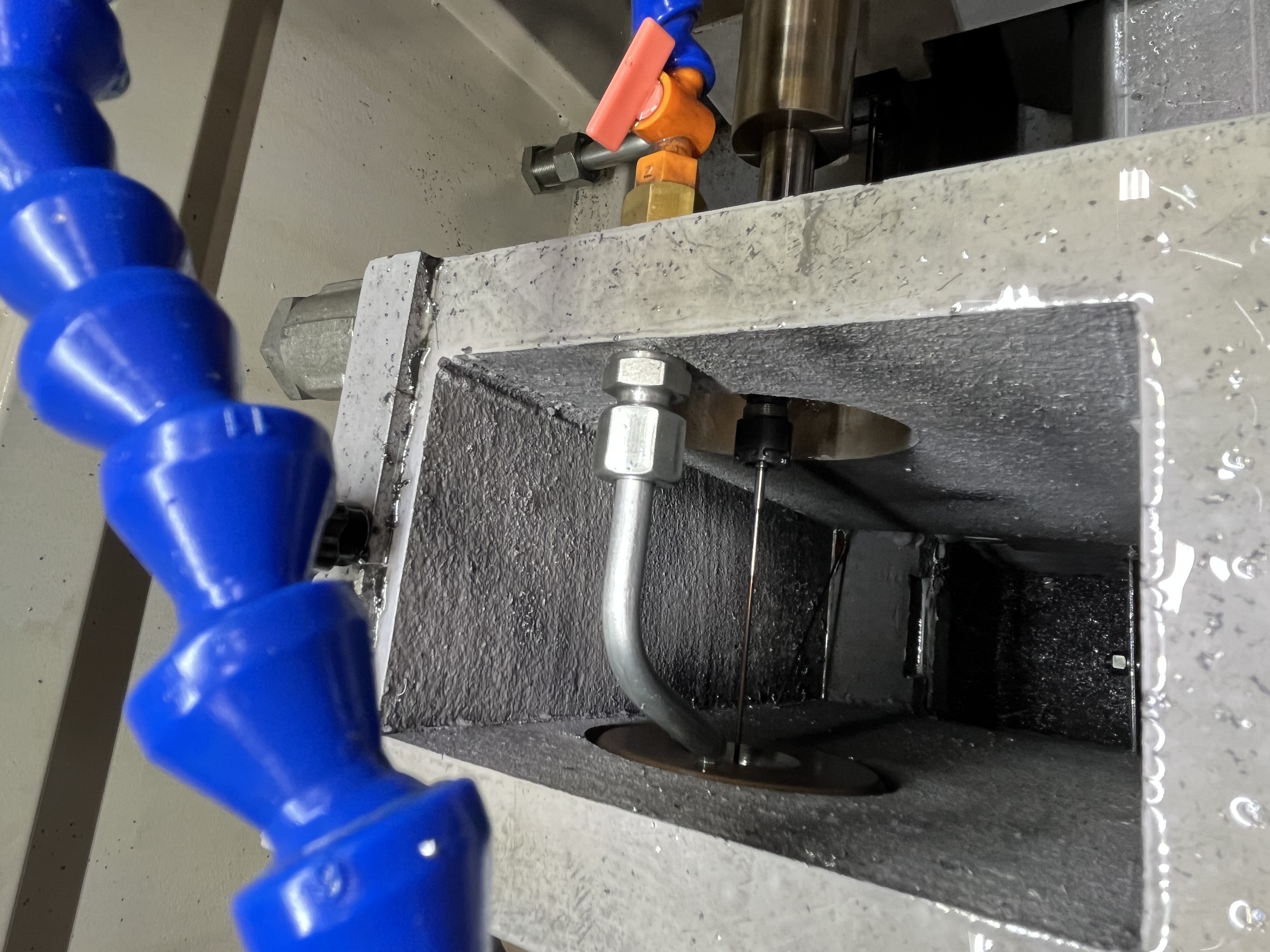
A test bar is a precision-ground bar that fits into the machine spindle. It extends from the spindle nose and is used to check the machine’s alignment. It’s a simple tool, but it’s essential for verifying machine condition.
I use a test bar for every machine installation and after any significant repair. The standard that governs this procedure is VDI 3212, which defines the acceptance test requirements for deep hole drilling machines with one or more spindles. I follow VDI 3212 as the baseline and adapt the tolerances based on the specific job requirements.
Test Bar Types and Selection
Test bars come in several configurations, and the right choice depends on what I am checking. Here is how the common types compare:
| Test Bar Type | Straightness Tolerance | Typical Length | Typical Diameter | Best For | Approximate Cost |
|---|---|---|---|---|---|
| Solid precision ground | 0.002 mm/m | 300 - 500 mm | 20 - 40 mm | Standard alignment check | $500 - $1200 |
| Extended length | 0.003 mm/m | 600 - 1000 mm | 25 - 50 mm | Long spindle extension check | $1000 - $2000 |
| Stepped (multiple diameters) | 0.002 mm/m | 300 - 500 mm | 10 - 40 mm | Multi-spindle concentricity | $800 - $1500 |
| Taper shank (Morse or CAT) | 0.002 mm/m | 200 - 400 mm | 20 - 30 mm | Quick spindle nose check | $600 - $1000 |
| Master test bar (certified) | 0.001 mm/m | 500 - 1000 mm | 30 - 50 mm | Calibration reference | $2000 - $5000 |
I keep a standard 400mm solid bar for daily checks and a master certified bar for annual calibration. The certified bar goes out for recertification every two years with a traceable calibration lab. The cost of recertification is about $300 and prevents me from chasing alignment errors that turn out to be a worn test bar.
For machines drilling holes over 1000mm deep, I use an extended-length test bar that covers at least half the drilling stroke length. A 200mm test bar on a machine with 2000mm of travel does not tell me anything about alignment at the far end — I learned this the hard way after chasing a taper problem that was actually a misalignment at mid-stroke.
What a Test Bar Does
The test bar simulates the centerline of the spindle. By measuring the position of the test bar at various points along its length, I can determine whether the spindle is aligned to the machine’s axis of travel.
The test bar is ground to a straightness of 0.002mm per meter or better. Any deviation measured on the test bar is the machine’s alignment error, not the bar’s error.
How to Use a Test Bar: Step-by-Step
I follow this procedure every time I check alignment. Skipping steps gives misleading results.
- Temperature stabilization — Run the spindle at operating speed for 30 minutes before measuring. A cold spindle has different thermal expansion than a hot spindle, and the alignment reading will be wrong if the machine is not at thermal equilibrium.
- Clean the spindle taper — Wipe the spindle bore or collet taper with a clean cloth and check for nicks or burrs. A chip embedded in the taper causes a false reading.
- Mount the test bar — Insert the test bar and tighten to the manufacturer’s torque specification. Overtightening distorts the bar. Undertightening lets it shift.
- Set up the dial indicator — Mount the indicator on the machine bed or table using a magnetic base. Position the indicator plunger perpendicular to the test bar surface. I use a 0.001mm resolution indicator for precision machines and a 0.01mm indicator for general checks.
- Zero at the spindle nose — Position the indicator to read the top of the test bar within 10mm of the spindle nose. Zero the indicator.
- Read at the far end — Slide the indicator base along the bed to the far end of the test bar without disturbing the indicator position. Record the reading.
- Repeat on the side — Move the indicator to read the side of the test bar and repeat steps 5 and 6. The side reading reveals horizontal misalignment that the top reading misses.
- Rotate the bar 180 degrees — Loosen the test bar, rotate it 180 degrees in the spindle, retighten, and repeat the measurements. Average the two readings to cancel out any residual error in the test bar itself.
The top reading tells me vertical alignment (the drill height relative to the guide bushing center). The side reading tells me horizontal alignment. Both need to be within tolerance.
Acceptance Criteria
The readings at the far end of the test bar tell you the spindle alignment error. I use these criteria based on VDI 3212 and my own experience:
| Measured Deviation (over 300mm) | Interpretation | Action Required |
|---|---|---|
| 0.01mm or less | Excellent alignment | No action needed |
| 0.01 - 0.02mm | Acceptable alignment | Monitor — recheck in 6 months |
| 0.02 - 0.05mm | Marginal — may cause issues on holes over 500mm deep | Investigate root cause and plan correction |
| Over 0.05mm | Poor alignment | Correct before production runs |
The tolerance depends on the machine and the work. A machine drilling 500mm holes can tolerate more alignment error than a machine drilling 2000mm holes. For holes deeper than 20x diameter, I use the excellent alignment threshold as my maximum allowable deviation.
I also check the difference between the near-end and far-end readings on the side of the bar. If the side deviation exceeds 0.02mm, the spindle axis is skewed relative to the guide bushing axis. This causes the drill to enter the workpiece at an angle and produces a curved hole. I wrote more about how a curved bore affects production quality in the vibration troubleshooting article.
Record Keeping and Trend Analysis
I keep a log for every machine alignment check. The log includes the date, the readings (top and side, near and far), the machine temperature, and the operator name. I use a simple spreadsheet that calculates the trend over time:
| Date | Top Deviation | Side Deviation | Machine Temp | Notes |
|---|---|---|---|---|
| 2026-01-15 | 0.008 mm | 0.006 mm | 28 C | Baseline — new machine |
| 2026-04-10 | 0.009 mm | 0.007 mm | 29 C | Within baseline |
| 2026-07-12 | 0.015 mm | 0.011 mm | 30 C | Drift detected, recheck in 3 months |
| 2026-10-05 | 0.022 mm | 0.018 mm | 28 C | Plan alignment correction |
I check alignment with a test bar:
- After machine installation
- After any spindle repair
- After moving the machine
- If hole quality drops unexpectedly
- At least quarterly for production machines (I used to do annual checks, but I found alignment drift accumulates faster than I expected)
Checking alignment quarterly catches alignment drift before it causes production problems. The trend data also tells me whether the drift is accelerating — a machine that goes from 0.008mm to 0.022mm in three quarters will likely need a spindle rebuild within the next year.
For machines that run critical tolerance parts, I also run a full machine capability study after a significant alignment correction. The capability study confirms that the alignment fix actually improved the process variation.
Key Takeaways
- I follow a 8-step test bar procedure that includes temperature stabilization, cleaning the spindle taper, measuring top and side, and rotating the bar 180 degrees to cancel test bar errors.
- The top reading reveals vertical alignment (drill height relative to guide bushing), and the side reading reveals horizontal alignment — both must be checked.
- I use VDI 3212 acceptance criteria: under 0.01mm is excellent, 0.01-0.02mm is acceptable, 0.02-0.05mm is marginal for long holes, and over 0.05mm requires immediate correction.
- A solid precision ground test bar costs $500-$1200 and works for standard checks, but I keep a master certified bar ($2000-$5000) for annual calibration reference.
- I check alignment quarterly instead of annually because I have found alignment drift accumulates faster than expected. Trend data in the log predicts when a spindle rebuild will be needed.
- The cost of a test bar is small compared to the cost of alignment problems in production.
- I run a machine capability study after significant alignment corrections to confirm the fix improved process variation.