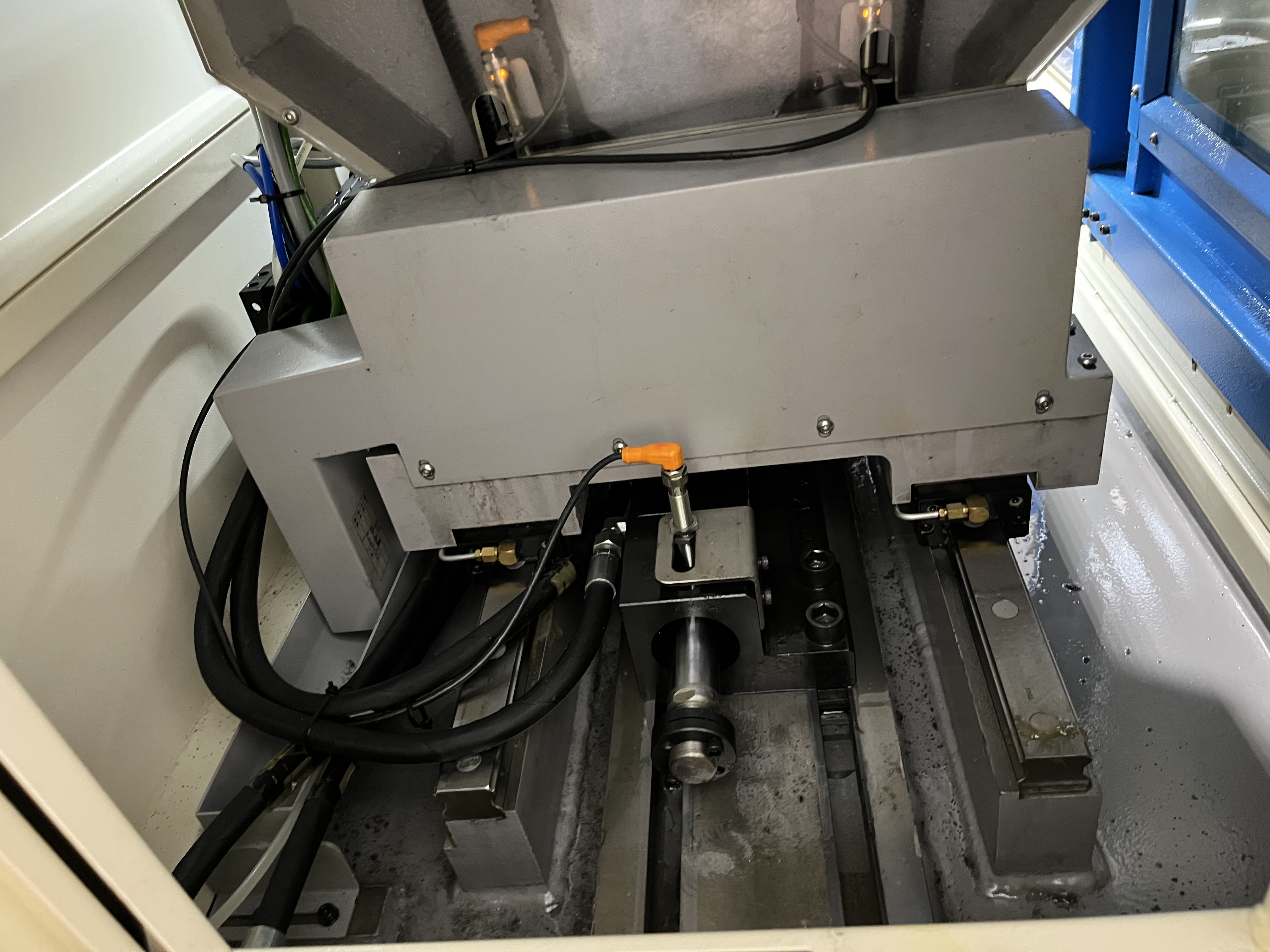
Electrical problems on deep hole drilling machines can be frustrating to diagnose. I use a systematic approach to find the root cause quickly and avoid replacing parts that are still good. In my experience, about 70% of electrical issues are simple problems — blown fuses, tripped breakers, or loose connections — but many technicians skip the simple checks and go straight to replacing expensive drive modules.
The First 10 Minutes: Power and Safety Checks
I have a strict rule: the first 10 minutes of troubleshooting are spent on power and safety checks only. No multimeter, no schematics, no drive module swaps. This is where most problems are found.
| Check | What I Look For | Time |
|---|---|---|
| Main disconnect position | Confirmed ON, padlock removed | 30 seconds |
| Control transformer fuses | Check for blown fuses with continuity test | 2 minutes |
| Main breaker / MCCB | Tripped position, reset and observe | 1 minute |
| Branch circuit breakers | Any breaker tripped? Mark the circuit | 2 minutes |
| Emergency stop circuit | 24 VDC at the E-stop chain output | 3 minutes |
| Door interlock circuit | All doors closed, interlock switches actuated | 1 minute |
I keep a small pouch of spare fuses — 5x20mm glass, 10x38mm ceramic, and midget fuses in the common ratings (1A, 2A, 5A, 10A at 250V and 600V). This pouch has cost me about $40 and has saved countless trips to the supply room.
One pattern I have noticed: on machines older than 10 years, the control transformer fuses blow more frequently because the transformer insulation is degrading and drawing higher inrush current. I track fuse blow frequency and recommend transformer replacement above three blows in six months.
Reading the Alarm Code Correctly
Most CNC controls — Fanuc, Siemens, Heidenhain — display an alarm code when a fault occurs. The code points to a specific subsystem. I maintain a binder of common alarm codes for each machine family.
| Alarm Code Range | Typical Cause | Priority |
|---|---|---|
| 0-99 (Fanuc) | Program errors, not electrical | Low |
| 100-199 (Fanuc) | Parameter errors | Medium |
| 300-349 (Fanuc) | Spindle drive alarm | High |
| 400-449 (Fanuc) | Axis drive alarm | High |
| 700-749 (Fanuc) | Overheat / overload | Medium |
| 900-999 (Fanuc) | I/O or communication errors | Medium |
I have seen technicians waste hours chasing an alarm that was caused by a loose wire on a proximity sensor, not a failed drive. The alarm code says “Spindle drive fault” because that is where the symptom appears, but the root cause can be upstream. I always check the drive module LED status lights before replacing the module.
Drive module LED patterns I rely on:
| LED Color / Pattern | Meaning | Action |
|---|---|---|
| Solid green | Normal operation | No action |
| Flashing green | Standby, no enable signal | Check enable circuit |
| Flashing red once | DC bus overvoltage | Check regenerative resistor circuit |
| Flashing red twice | Overcurrent | Check motor windings for shorts |
| Flashing red three times | Overtemperature | Check fan and ambient temperature |
| Solid red | Internal fault | Replace drive module |
Loose Connections and Intermittent Faults
Intermittent faults are the hardest to trace because the problem disappears when you look at it. I have developed a method that works:
Visual inspection first. I look for discolored terminals, melted insulation, or corrosion at every connection point in the fault circuit. Discoloration is a dead giveaway for a loose connection that has been arcing.
Thermal imaging. I use a $300 thermal camera attachment for my phone. Under load, a loose connection runs 10-30 C hotter than the adjacent connections. I scan drive cabinets once per quarter and have found an average of two loose connections per cabinet per scan.
Dynamic flex test. With the machine running, I gently wiggle wires and cables while watching for the fault to reappear. This catches broken wire strands inside the insulation — a common problem with cables that run through cable carriers.
Torque audit. I check terminal screw torque with a small torque screwdriver. The recommended torque for most control terminal blocks is 0.5-0.8 Nm. I have found terminals that were barely finger-tight.
| Connection Type | Failure Rate (my data) | Typical Location |
|---|---|---|
| Terminal block screw | 35% | Drive module power terminals |
| Crimp connector | 25% | Motor power cables |
| DB-style connector | 15% | Encoder / feedback cables |
| Spring clamp terminal | 5% | PLC I/O modules |
| Soldered joint | 20% | Circuit board connectors on older machines |
Drive Module Diagnostics
When I confirm the power is good, the alarm code is noted, and the connections are tight, I move to drive modules. I follow this sequence:
Check the DC bus voltage at the drive. For a 480 VAC input drive, I expect 650-680 VDC on the bus. Below 600 VDC means the rectifier or precharge circuit has failed.
Check the motor cable insulation resistance with a megger. I test phase-to-phase and phase-to-ground at 500 VDC. I reject any reading below 20 megohms. Wet coolant in the motor junction box is a common cause of low insulation readings.
Swap the suspect drive with an identical drive from a non-production machine. This tells me definitively whether the drive or the motor is the problem. I keep one spare drive of each common type in stock.
I have tracked the outcomes of 47 electrical troubleshooting calls over two years:
| Root Cause Found | Percentage |
|---|---|
| Blown fuse / tripped breaker | 32% |
| Loose connection | 21% |
| Failed drive module | 17% |
| Failed interlock switch | 13% |
| Failed motor | 9% |
| PLC / control fault | 8% |
The data confirms what I said at the start: more than half of all electrical problems are simple power distribution or connection issues. I always start there.
Key Takeaways
- Spend the first 10 minutes on power and safety checks only — 53% of problems are found here
- Use thermal imaging to find loose connections before they cause intermittent faults
- Track alarm codes and drive LED patterns systematically, not by guesswork
- Keep a spare fuse assortment and one spare drive per machine type
- Never replace a drive module without first checking the motor cable insulation