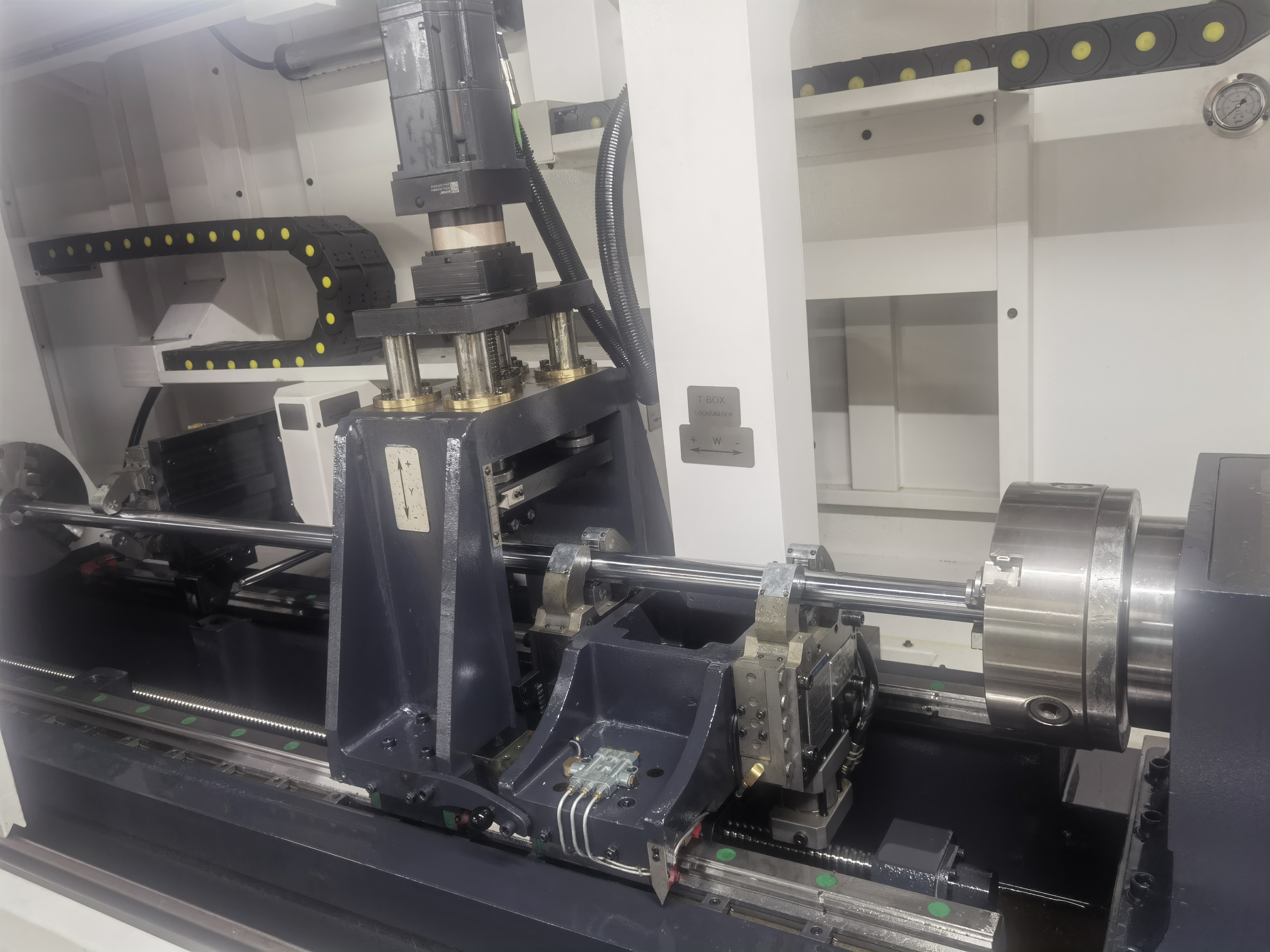
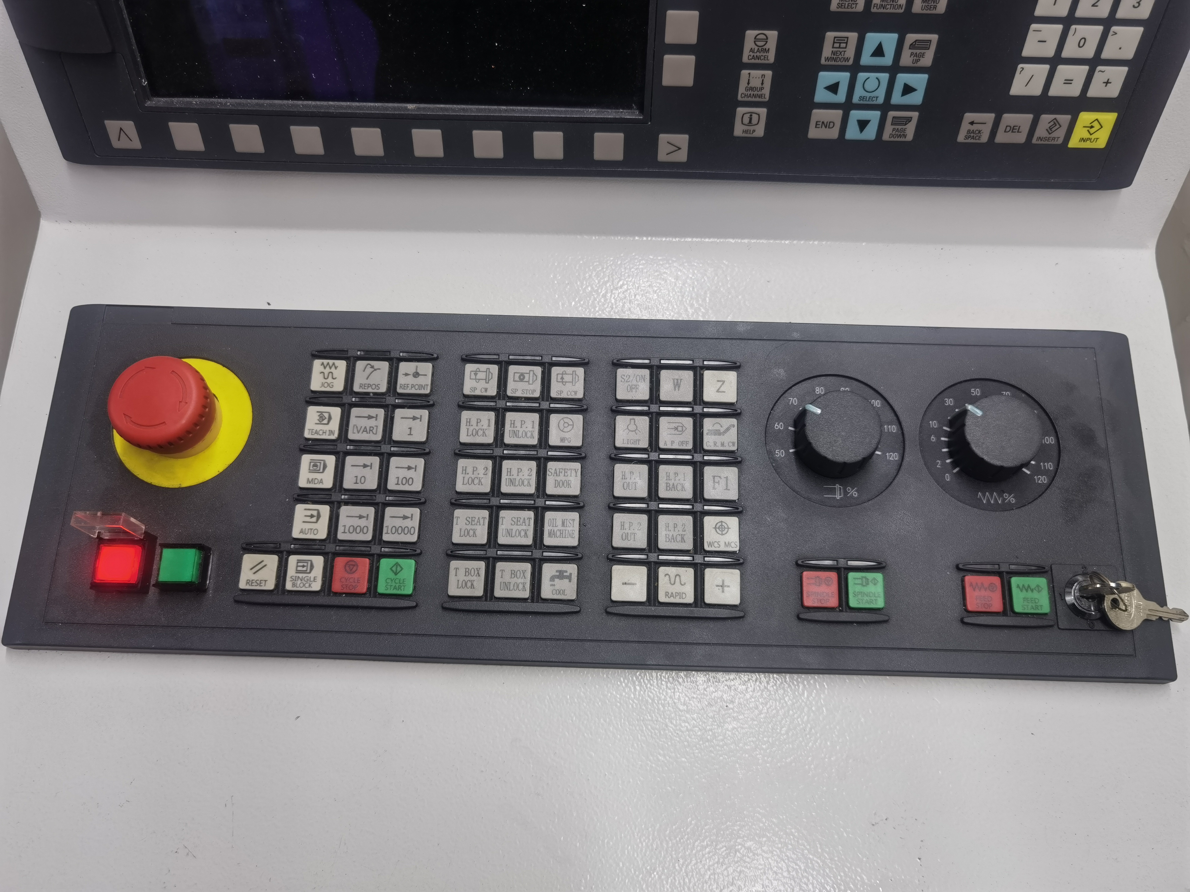
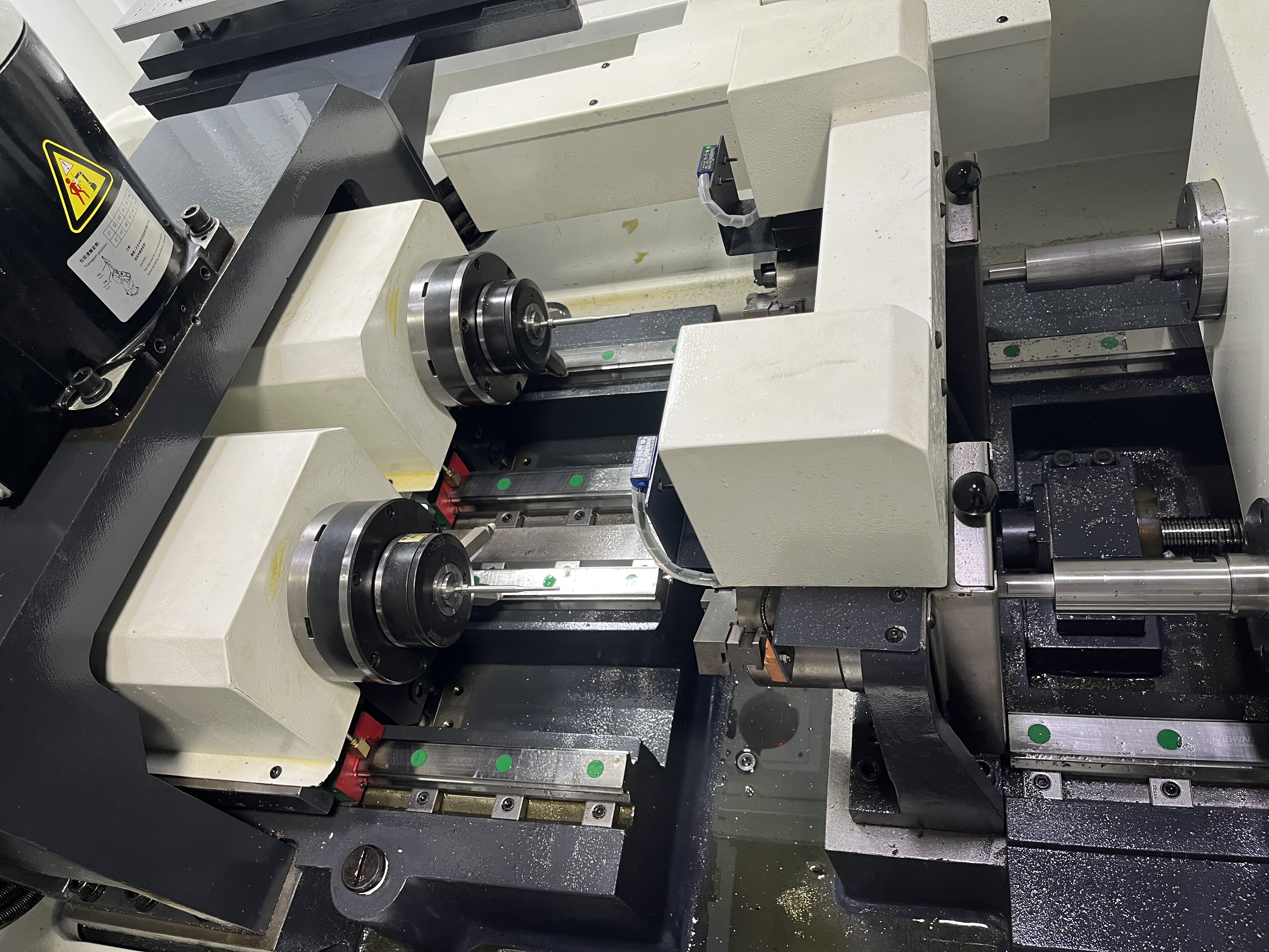
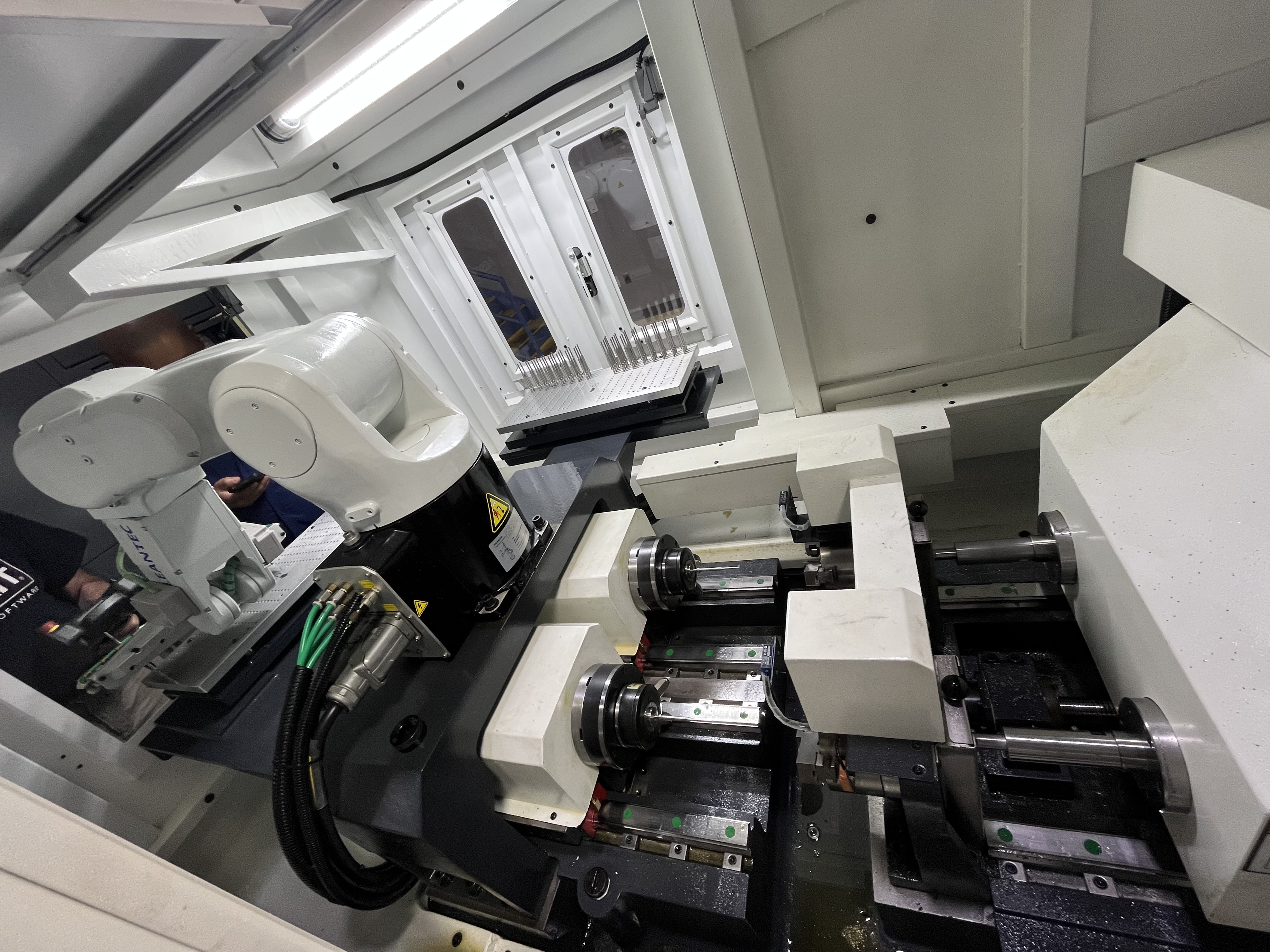
Real problems, real solutions, no fluff. I have spent years working across multiple shops running gun drilling, BTA drilling, and ejector drilling machines — setting up jobs, troubleshooting coolant pressure and chip evacuation issues, drilling deep holes in everything from hydraulic cylinders to aerospace titanium. This site is where I share what I have learned.
How to Improve Gun Drilling Surface Finish: Parameters, Tool Geometry, and What Actually Works
I have spent years chasing better surface finishes in gun drilled holes. The difference between a Ra 0.8μm hole and a Ra 0.2μm hole is not just feed rate — it is a combination of parameters, tool geometry, and process conditions that most operators do not connect. Here is what I have learned about each variable and how much it actually matters. Feed Rate: The Biggest Lever Feed rate is the single most influential parameter for surface finish. Every 0.01mm/rev increase in feed adds visible feed marks. The relationship is direct and measurable. ...
How to Use a Laser Interferometer for Machine Calibration
A laser interferometer measures machine positioning accuracy with sub-micron resolution. I use one for annual calibration of production deep hole drilling machines. The first time I ran a full laser calibration on a machine that was supposedly within spec, I found positioning errors of 0.08 mm per meter — four times the acceptable limit. The compensation corrected those errors and improved the hole position repeatability from 0.05 mm to 0.01 mm. ...
Hydraulic Cylinder Deep Hole Drilling: Honing Stock, Bore Finish, and What I Leave for the Hone
I have drilled thousands of hydraulic cylinder barrels at this point, and if there is one question that comes up every time I walk into a new shop it is this: how much do I leave for the hone? The answer is never the same number twice. It depends on bore diameter, length, material, drilling method, and how straight the bore comes out of the machine. This article is the guide I wish I had when I started — what I leave for the hone, how I decide, and what tells me I have got it wrong. ...
Hydraulic Cylinder Drift Diagnosis on Deep Hole Drills
Hydraulic cylinder drift on deep hole drilling machines causes the feed axis to move when it should stay in position. This drift can advance the drill into the bore when it should be retracting, causing tool damage, or it can let the spindle head sag during a tool change, making alignment impossible. I have debugged drift problems on machines ranging from small gun drills to large BTA systems with 10-ton feed forces. ...
Hydraulic vs Mechanical Tool Holders for Gun Drills
The tool holder connects the gun drill to the machine spindle. The holder runout directly affects hole quality, tool life, and process consistency. A holder with high runout produces oversized holes, poor surface finish, and premature tool failure. I treat tool holder selection as a process-critical decision, not an afterthought. How Each Holder Type Works Hydraulic tool holders use oil pressure to clamp the drill shank. Turning a screw pressurizes oil in a sealed chamber, which expands a thin steel sleeve that grips the shank evenly around its full circumference. The clamping force is consistent and does not deform the shank because the pressure distributes uniformly. A hydraulic chuck gives the same runout every time regardless of operator skill. ...
I Ignored the Chip Shape and Scrapped a Hundred Parts
Reading chips is one of those skills that separates real deep hole drillers from everyone else. The chips tell you everything — coolant pressure, feed rate, tool condition, material consistency, heat generation. They’re like a conversation the machine is having with you in real time. The problem is, sometimes you don’t want to hear what they’re saying. You’re on a deadline, you’re tired, you’ve got pressure from above to keep the parts coming, and it’s easier to tell yourself the chips look “close enough.” ...
I Skipped the Warm-Up and Scrapped a $2,000 Part
It was a Monday morning in January, the shop was freezing, and I was behind schedule. The weekend crew had left a machine set up and ready to run, and the part on the table was a large hydraulic cylinder block that had already gone through several operations. All it needed was a 25mm hole drilled 800mm deep. About an hour of cycle time, then on to the next operation. ...
I Took a Coolant Pump Apart and Found a Rag
We had a machine that had been losing coolant pressure for about three months. Not dramatically, but steadily. The pressure at the tool had gone from 1200 psi down to about 900 psi, and it kept dropping a little more every week. I had changed the filter elements. I had checked the pump motor current. I had inspected the pressure relief valve. Nothing helped. The machine was still making good parts, so the slow pressure loss got treated as a low priority. The operators adjusted their peck cycles to compensate for the reduced chip clearing. The production schedules got padded to account for the longer cycle times. Everybody just worked around it. ...
I Tried Gun Drilling and It Broke: A Post-Mortem of First-Time Failures
I have had this conversation a dozen times. A shop calls and says they tried gun drilling on a manual lathe, snapped the drill in the first hole, and want to know what went wrong. The answer is almost always the same: coolant pressure, pilot hole, or feed rate. Sometimes all three. Here is what I see most often. Failure 1: Not Enough Coolant Pressure This is the #1 first-time killer. A standard lathe coolant pump puts out 20-50 psi. Gun drilling needs 500-3000 psi depending on diameter. The difference is not subtle — at 50 psi, chips do not move. They pack behind the drill and the torque spikes until something breaks. ...
Integrating In-Process Gauging with Machine Control
Integrating in-process gauging with the machine control allows automatic measurement of the bore diameter during the drilling cycle. The gauge measures the bore immediately after drilling and the control records the data, adjusts parameters, or alerts the operator. I have implemented these systems on several production machines and the improvement in quality consistency has been substantial. System Architecture and Components The in-process gauging system consists of a measuring probe, a data interface, and the CNC control integration. The measuring probe can be an air plug or a contact probe mounted near the spindle or on a separate slide. ...