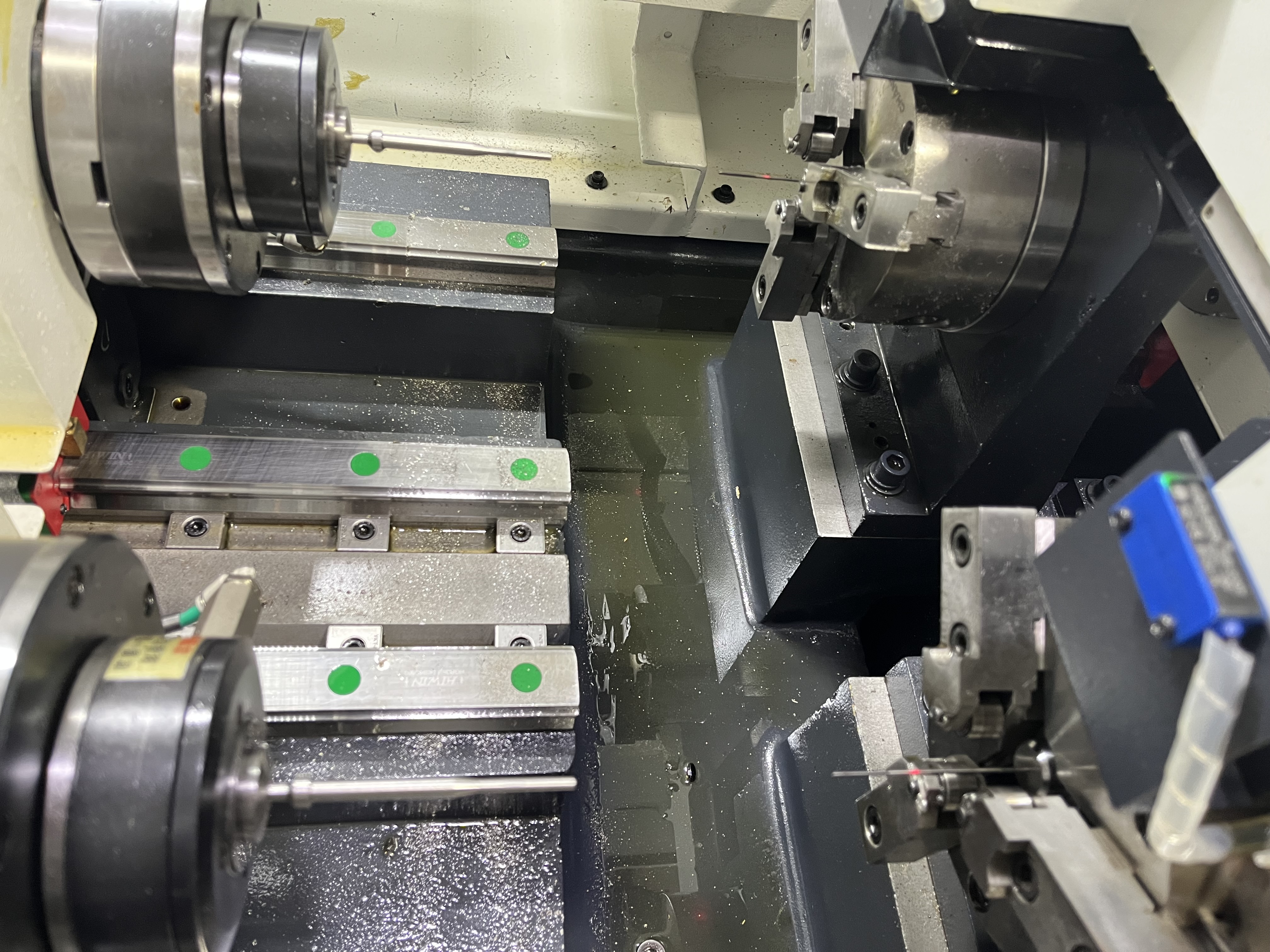
I maintain the coolant system regularly because it causes the most problems. Roughly 60% of the unplanned downtime I have seen on deep hole drilling machines traces back to the coolant system.
The coolant system is the heart of a deep hole drilling machine. Without it, the machine cannot function. The coolant flushes chips, lubricates the cutting zone, and controls temperature. A poorly designed system causes scrapped parts, broken tools, and days of troubleshooting.
This guide covers the design decisions I have made and the mistakes I have learned from.
System Architecture Overview
A deep hole drilling coolant system has six main subsystems that work in sequence:
- Coolant tank — stores and settles coolant
- Pump — provides pressure and flow
- Filter system — removes chips and contamination
- Chiller or heat exchanger — controls temperature
- Piping and rotary union — delivers coolant to the tool
- Return line — carries coolant and chips back to the tank
Every subsystem must be sized correctly for the others to work. I learned this the hard way when I upsized the pump without upsizing the return line and flooded the shop floor.
Tank Sizing
The coolant tank serves two functions: storage and settling. Chips need time to fall out of suspension before the coolant returns to the pump intake.
My rule of thumb: tank volume should be at least 3x the pump flow per minute. For a 20 gpm pump, that means a 60-gallon tank minimum.
Better rule: 5x for systems that run aluminum or stainless. Aluminum chips are light and stay in suspension longer. Stainless chips are thin and do not settle quickly. I run a 120-gallon tank for a 20 gpm pump on stainless jobs and still see fine chips in the clean side.
| Pump Flow | Minimum Tank (3x) | Recommended Tank (5x for Al/SS) |
|---|---|---|
| 10 gpm | 30 gallons | 50 gallons |
| 20 gpm | 60 gallons | 100 gallons |
| 30 gpm | 90 gallons | 150 gallons |
| 50 gpm | 150 gallons | 250 gallons |
Baffle design matters. The tank needs baffles between the return and pump compartments. Without baffles, chips recirculate. I use two baffles with a 50 mm gap at the bottom — the first settles large chips, the second traps fines. The return line dumps into the first compartment and the pump draws from the last.
Chip conveyor. For production systems, add a hinge-belt chip conveyor in the first compartment. Manual chip removal stops being practical above 10 gallons of chips per shift.
Pump Selection
The pump is the most critical component. Get the pressure and flow wrong and nothing else matters.
Centrifugal Pumps
Centrifugal pumps are the cheapest option. They deliver high flow at low to moderate pressure. I only use centrifugal pumps for low-pressure flushing systems and coolant transfer. For any drilling application above 200 psi, do not use a centrifugal pump — the pressure drops as flow increases and the tool starves.
Positive Displacement Pumps
This is what I use for most deep hole drilling. Positive displacement pumps deliver consistent pressure regardless of flow changes. A screw pump or gear pump holds pressure steady at the tool tip even when the drill enters and exits the workpiece.
I run a progressive cavity pump on my main machine. It delivers 20 gpm at 1,000 psi with less than 2% pressure variation across the flow range. The pump cost 3x a centrifugal but has run for four years without a rebuild.
Piston Pumps
Piston pumps deliver very high pressure (5,000+ psi) at low flow. I use a piston pump for a micro-drilling application — 0.5 gpm at 3,000 psi for 2 mm holes. Piston pumps are noisy, require frequent seal changes, and produce pressure ripple that needs a damper. Only use them when you genuinely need the pressure.
Pump Comparison
| Pump Type | Pressure Range | Flow Range | Pressure Stability | Relative Cost | Maintenance Interval |
|---|---|---|---|---|---|
| Centrifugal | 20–200 psi | 10–100 gpm | Poor | 1x | 12 months |
| Progressive cavity | 100–1,500 psi | 1–50 gpm | Excellent | 3x | 24 months |
| Gear (external) | 200–2,000 psi | 1–30 gpm | Very good | 2.5x | 18 months |
| Piston (axial) | 500–5,000 psi | 0.1–10 gpm | Good (with damper) | 5x | 6 months |
Piping Layout
Piping design is as important as pump selection. Bad piping creates pressure drops that reduce effective pressure at the tool.
Pipe diameter. I size the supply line for a maximum velocity of 3 m/s. Above 3 m/s, pressure drop rises fast and you lose pressure before the coolant reaches the tool.
Table: Recommended Pipe ID by Flow Rate
| Flow Rate | Recommended Pipe ID | Pressure Drop per 10m (at 1,000 psi supply) |
|---|---|---|
| 5 gpm | 1/2 inch | 15 psi |
| 10 gpm | 3/4 inch | 12 psi |
| 20 gpm | 1 inch | 18 psi |
| 30 gpm | 1-1/4 inch | 14 psi |
| 50 gpm | 1-1/2 inch | 20 psi |
Return line. The return line must be larger than the supply line — I size it for 2 m/s max velocity. Chips in the return flow increase back pressure. A return line that is too small causes chip packing that stops the machine.
Fittings and elbows. Each 90-degree elbow adds the equivalent of 30–50 pipe diameters of straight pipe in pressure drop. I use long-radius elbows and minimize fittings between the pump and the spindle. On one machine, I cut pressure drop by 40% by replacing four 90-degree elbows with a single curved hose.
Flexible hoses. Use reinforced hoses rated for the maximum pump pressure plus 50% safety margin. I use wire-braided hoses on all high-pressure lines. Standard hydraulic hoses fail after six months in water-based coolant.
Filtration Stages
Coolant filtration directly affects tool life. A study I read claims 80% of tool wear comes from recirculating chips. I believe it based on what I have seen.
Stage 1 — Chip Conveyor / Scraper
Removes bulk chips from the return flow before coolant enters the settling tank. Hinge-belt conveyors work well for steel chips. Magnetic separators work for ferrous materials. I use a magnetic drum separator on my aluminum line because aluminum chips float.
Stage 2 — Gravity Settling
The baffled tank design above. Allows chips to settle out of suspension. Targets particles above 100 microns.
Stage 3 — Cartridge or Bag Filter
Catches particles down to 20–50 microns. I use bag filters with replaceable elements. The filter housing must be sized for the full pump flow at 2x the micron rating — using a 25-micron filter on a line with 50-micron particles means constant clogging.
Filter sizing rule: filter area should provide at least 5 gpm per square foot of media at the target micron rating. Under-sized filters clog in minutes and starve the pump.
Stage 4 — Optional Polishing Filter
For finishing work below 10 micron surface finish requirement, I add a polishing filter after the main pump. This is a side-loop that pulls from the clean tank, filters to 5 microns, and returns. It adds cost but improves surface finish by 30–50%.
Temperature Control
Coolant temperature stability is underrated. Temperature changes alter hole diameter through thermal expansion of the workpiece and tool.
Target temperature: 20–25°C for most applications. I hold it within 2°C during production runs.
Why temperature matters: A 5°C temperature change in a 500 mm steel workpiece changes its length by 0.06 mm. That is enough to push hole diameter out of tolerance on precision work.
Chiller sizing: I size the chiller to handle the total heat load. A rough rule is 1 ton of cooling (12,000 BTU/hr) for every 5 hp of cutting power. For a 15 hp spindle running at 80% load, I use a 3-ton chiller minimum.
Alternatives: In winter, a simple plate heat exchanger with city water bypass works well for machines running fewer than 8 hours per shift. I use this on a backup machine and it holds temperature to 25 ± 3°C without a chiller.
Coolant concentration. I check concentration weekly with a refractometer. Water-based coolant at 5–8% concentration provides the best cooling and lubrication balance. Below 4%, rust and bacteria grow. Above 12%, cooling capacity drops and the coolant leaves sticky residue.
Rotating Union Selection
The rotating union transfers coolant from the stationary pipe to the rotating spindle. It is a wear item that causes intermittent problems.
Key specs: Pressure rating, speed rating, and seal material. I use unions rated for 1.5x the pump pressure and 1.2x the spindle speed. Silicon carbide seals last 2–3x longer than carbon seals in water-based coolant.
Common failure mode: The union leaks slowly, then suddenly the seal fails completely and coolant floods the spindle bearings. I replace rotating unions every 2,000 hours of spindle runtime whether they leak or not.
Maintenance Schedule
| Task | Frequency | What Happens If You Skip It |
|---|---|---|
| Check coolant concentration | Weekly | Rust, bacterial growth, poor lubrication |
| Clean tank and baffles | Monthly | Chip buildup reduces settling efficiency |
| Replace bag/cartridge filters | Per schedule or at 10 psi pressure drop | Pump starvation, pressure loss at tool |
| Inspect hoses and fittings | Monthly | Burst hose at high pressure |
| Check rotating union seals | Every 500 hours | Coolant leak into spindle bearings |
| Replace rotating union | Every 2,000 hours | Catastrophic seal failure |
| Clean chip conveyor | Weekly | Jammed conveyor, tank overflow |
| Check chiller refrigerant | Quarterly | Temperature drift out of tolerance |
| Inspect pump seals | Monthly | External coolant leak, pump cavitation |
I put these tasks in the machine maintenance log with a sign-off column. Without the sign-off, they do not get done.
Troubleshooting Common Coolant Problems
Pressure at the tool is lower than pump pressure. Check filters first. A clogged filter is the cause 80% of the time. If filters are clean, check piping for kinks, a clogged rotary union, or a worn pump.
Chips are not evacuating. Low flow, not low pressure. Check the return line for blockages. Check pump flow rate. A 20% flow drop causes chip evacuation failure before it shows on the pressure gauge.
Coolant temperature is rising. Chiller undersized or not cycling. Check the chiller setpoint and refrigerant level. If those are fine, the pump may be generating more heat than the chiller can reject.
Foaming coolant. Air is entering the system. Check the return line for vortex at the tank inlet. Check pump inlet for air leaks. Add defoamer as a temporary fix, fix the air leak permanently.
Key Takeaways
- Size the coolant system for the largest hole you plan to drill, not the average hole.
- Tank volume is cheap. Oversize it by 50% from the start.
- A good filter system pays for itself in tool life within six months.
- Positive displacement pumps are worth the cost for gun drilling and BTA work.
- Temperature control separates precision shops from the rest.
- The rotating union is the weakest link — replace it on schedule, not when it leaks.
- Document the system design. Six months after installation, you will not remember exactly how it was piped.
- Related: See Chip Formation in Deep Hole Drilling for how chip shape interacts with coolant performance.