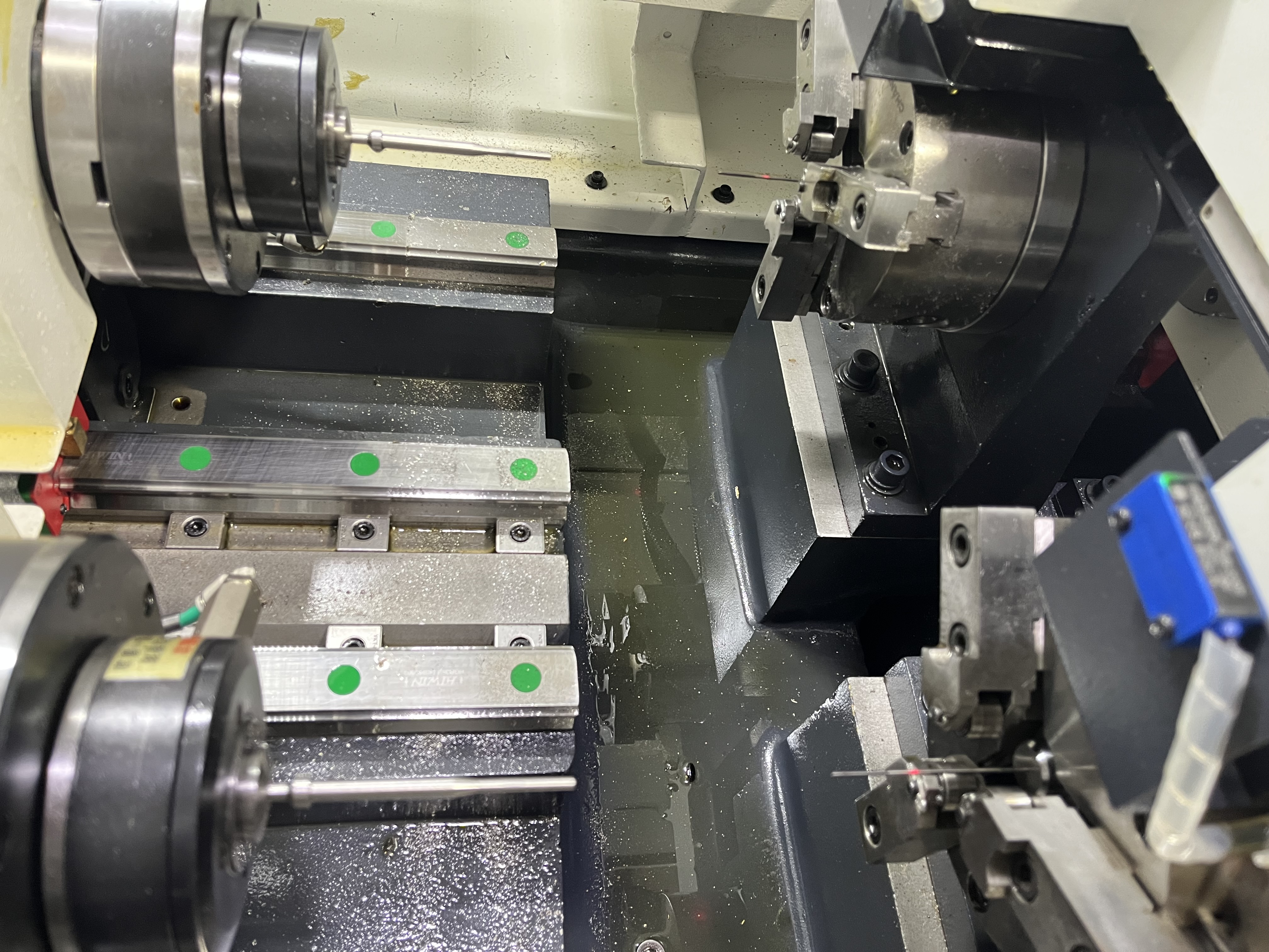
I have spent years chasing better surface finishes in gun drilled holes. The difference between a Ra 0.8μm hole and a Ra 0.2μm hole is not just feed rate — it is a combination of parameters, tool geometry, and process conditions that most operators do not connect.
Here is what I have learned about each variable and how much it actually matters.
Feed Rate: The Biggest Lever
Feed rate is the single most influential parameter for surface finish. Every 0.01mm/rev increase in feed adds visible feed marks. The relationship is direct and measurable.
| Feed (mm/rev) | Expected Ra in Steel (μm) | Feed Mark Spacing |
|---|---|---|
| 0.010 | 0.2-0.4 | Fine, barely visible |
| 0.020 | 0.4-0.6 | Visible under magnification |
| 0.030 | 0.6-0.9 | Visible to the eye |
| 0.040 | 0.9-1.3 | Clearly visible |
| 0.050 | 1.3-1.8 | Rough |
For the best finish, I run the lowest feed that still produces broken chips. If the feed is too low, the chip becomes a long string that can scratch the bore surface as it exits. The sweet spot for most materials is 0.015-0.025mm/rev — low enough for good finish, high enough for chip control.
I cover the full speed/feed reference in Gun Drilling Speeds and Feeds.
Spindle Speed: Higher Is Better for Finish
Within the recommended speed range for the material, higher spindle speed improves surface finish. The cutting edge passes more frequently, reducing the height of each feed mark.
For a 10mm gun drill in medium carbon steel:
- At 2000 RPM (160 SFM): Ra typically 0.6-0.8μm
- At 3500 RPM (275 SFM): Ra typically 0.3-0.5μm
The trade-off is tool life. Higher speed wears the cutting edge faster. I find the best balance at 70-80% of the maximum recommended speed for that material. This gives good finish without sacrificing tool life.
Tool Geometry: What the Numbers Actually Mean
The cutting edge geometry directly affects the surface the tool leaves behind. Small changes in angles produce measurable differences in Ra.
Point angle. A wider point angle (130-140 degrees) produces a smoother finish because it spreads the cutting force across more edge. Narrower angles (110-120 degrees) penetrate faster but leave a rougher surface. For finish-critical work, I use 135 degrees.
Tip radius. A larger tip radius (0.03-0.05mm) burnishes the surface as it cuts, reducing Ra by 0.1-0.2μm compared to a sharp tip. But it also increases cutting forces. I use a radius for finish passes and a sharp edge for roughing.
Guide pad design. The guide pads burnish the bore surface as the drill rotates. A three-pad design burnishes more evenly than a two-pad design and produces measurably better Ra values. The pads must be in good condition — worn or galled pads will scratch the surface rather than burnish it.
I cover geometry selection in detail in Gun Drill Geometry Guide.
Coolant Pressure and Filtration
Coolant affects surface finish in two ways: chip evacuation and edge lubrication.
If chips are not cleared efficiently, they scratch the bore surface on the way out. I have traced rough surface finish to inadequate coolant pressure more times than I care to count. The minimum pressure for good chip evacuation is covered in Coolant Requirements by Diameter.
Filtration matters. Chips recirculating in the coolant act as abrasive particles that score the bore surface. I use 20-micron filtration for finish-critical gun drilling. At 50 microns, particles large enough to scratch a Ra 0.4μm surface pass through.
Tool Coating Effect
Coatings reduce friction between the cutting edge and the workpiece. Less friction means lower cutting forces and a smoother surface.
| Coating | Effect on Ra vs Uncoated | Best For |
|---|---|---|
| TiAlN | 10-15% improvement | Steel, stainless |
| AlCrN | 15-20% improvement | Titanium, superalloys |
| TiN | 5-10% improvement | General purpose |
| DLC | 20-30% improvement | Aluminum, non-ferrous |
For the best surface finish, AlCrN or DLC coatings produce the lowest Ra values. I cover coating selection in Gun Drill Coatings.
Material-Specific Adjustments
Different materials respond differently to the same parameters. Here is what I adjust for each:
Steel (4140, 1045). Standard parameters work well. Feed rate is the main lever — drop feed by 0.005mm/rev and Ra improves by 0.2μm.
Stainless steel (304, 316). Prone to work hardening that degrades surface finish. Keep feed above 0.015mm/rev to avoid rubbing. Use AlCrN coating. I cover this in Stainless Steel Deep Hole Drilling.
Aluminum. Soft and gummy. Low feed rates (0.010-0.015mm/rev) combined with high speed and oil-based coolant produce the best finish. Avoid water-based coolant — it degrades finish. I cover this in Gun Drilling Aluminum.
Titanium. Work-hardens aggressively. Feed rate must stay above 0.020mm/rev. Higher coolant pressure (1500+ psi) improves chip evacuation and prevents scratches from packed chips. I cover this in Titanium Parameters.
When As-Drilled Finish Is Not Enough
If the as-drilled finish does not meet the specification, I use one of these secondary operations:
| Method | Ra Improvement | Material Removed | Cost vs Gun Drilling |
|---|---|---|---|
| Reaming | Ra 0.6 → 0.3μm | 0.1-0.3mm | 20-30% |
| Honing | Ra 0.6 → 0.1μm | 0.05-0.15mm | 40-60% |
| Skiving & burnishing | Ra 0.6 → 0.05μm | 0.1-0.3mm | 50-80% |
I choose the method based on the required finish and the amount of stock available. Honing is the most forgiving. Skiving and burnishing is the fastest but needs more stock.
Key Takeaways
- Feed rate is the biggest lever. Dropping feed by 0.005mm/rev improves Ra by approximately 0.2μm.
- Higher spindle speed improves finish up to 70-80% of the maximum recommended speed for that material.
- Tool geometry matters — use a 135-degree point angle and radiused tip for finish-critical work.
- Coolant filtration at 20 microns or better prevents recirculating chips from scratching the bore.
- DLC and AlCrN coatings produce the best surface finish, especially in aluminum and titanium.
- If as-drilled finish is not enough, honing or skiving and burnishing can improve Ra by 3-10x.