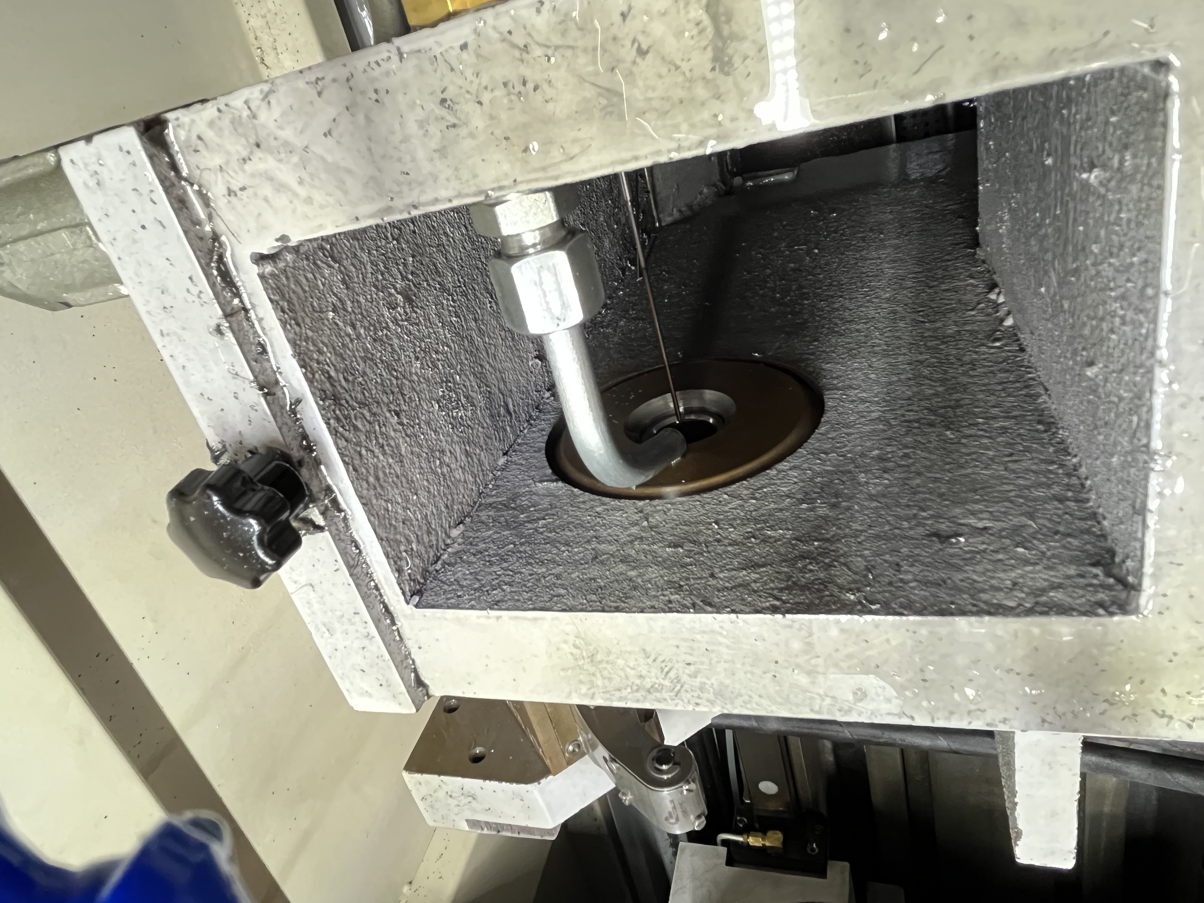
I reduce feed through cross holes to protect the drill from shock loading. When a gun drill passes through a cross hole, the cutting edge loses contact with the material momentarily and then re-enters on the far side. The impact of re-entry chips the cutting edge if the feed is too high. I learned this the hard way on a batch of hydraulic manifold blocks where I chipped three drills in a row before I figured out the feed reduction.
Cross Hole Types and Risk Assessment
Not all cross holes are the same. The geometry of the intersection determines the level of risk to the drill and the strategy I use. I classify cross holes into four types based on their orientation and size relative to the main bore.
| Cross Hole Type | Orientation | Relative Size | Interruption Type | Risk Level | Recommended Feed Reduction |
|---|---|---|---|---|---|
| Perpendicular, smaller | 90°, < drill dia | Smaller | Partial | Low | 0-30% |
| Perpendicular, equal | 90°, = drill dia | Equal | Full | Medium | 40% |
| Perpendicular, larger | 90°, > drill dia | Larger | Full + chip trap | High | 50% |
| Angled, < 90° to axis | 30-75° | Any | Gradual entry/exit | Medium-High | 40-50% |
| Angled, > 90° to axis | 105-150° | Any | Shock re-entry | High | 50-60% |
| Multiple in sequence | Various | Any | Repeated interruptions | Very High | 40% each + pecks |
| Slot or pocket | Parallel | Wider than drill | Extended void | Extreme | 60% + pilot hole |
Angled cross holes are more dangerous than perpendicular ones. When the cross hole enters the bore at an acute angle, the drill cutting edge experiences a gradual loss of contact on one side and a sudden re-entry on the other. This uneven loading twists the drill and can cause it to walk off-course.
Feed Management at Interruptions
I reduce the feed by about 40% for the 5mm before the cross hole and return to normal feed 5mm after. This gives the cutting edge a gentler re-entry into the material on the far side. I program this feed change into the CNC cycle so it happens automatically — the operator should not have to remember to adjust it.
The feed reduction zone needs to account for the cross hole width. For a 10mm diameter cross hole, I program the feed reduction to start 5mm before the hole (at 10mm from the cross hole center) and end 5mm after (at 10mm past the center). The total reduced-feed zone is 20mm.
For multiple cross holes along the bore axis, I program a separate feed reduction for each one. The machine executes them in sequence as the drill advances. A part with four cross holes might have four separate feed reduction zones in the program.
| Cross Hole Size vs Drill Dia | Interruption Type | Feed Reduction | Additional Actions | Tool Risk |
|---|---|---|---|---|
| Smaller than drill dia | Partial | 0-30% | None, or post-hole inspection | Low |
| Equal to drill dia | Full | 40% | Post-hole peck | Medium |
| Larger than drill dia | Full + chip trap | 50% | Retract after hole, flush cycle | High |
| Multiple holes (3+) | Multiple full | 40% each | Add peck between each, reduce speed | Very High |
| Angled entry | Gradual partial | 40-50% | Reduce speed 20% as well | High |
| Slot or pocket | Extended void | 60% | Pilot hole recommended | Extreme |
Partial vs Full Interruptions
The size of the cross hole matters for determining the risk. A cross hole that is smaller than the drill diameter causes a partial interruption — part of the cutting edge stays in contact while the rest passes over the void. This is less damaging than a full interruption because the edge never fully exits the cut.
I have drilled through 6mm cross holes with an 8mm gun drill at full feed and seen no damage. The partial contact keeps the cutting edge in compression and prevents the impact loading that chips the carbide. The only issue was a small burr at the intersection that needed deburring afterward.
A cross hole that is larger than the drill diameter causes a complete interruption. The entire cutting edge loses contact and slams into the far side wall. I have seen complete interruptions chip 0.5mm off the cutting edge in a single pass. For full interruptions, I always reduce feed and add a peck retract after the cross hole.
Tool Selection for Interrupted Cuts
When I know a job has cross holes, I select the tooling differently. Standard gun drills with a single guide pad are more prone to damage at interruptions. I switch to double-margin gun drills or drills with extended guide pads for cross-hole work.
The extended guide pad provides more surface contact with the bore wall, which stabilizes the drill during the interruption. Gühring’s EB 80 series with a longer straight guide section is my preferred choice for jobs with multiple cross holes. I have measured half the hole curvature deviation with extended guide pad drills compared to standard gun drills when drilling through cross holes.
For partial interruptions, a standard gun drill is usually fine. For full interruptions, I always use a double-margin drill. The extra margin on the opposite side keeps the drill tracking straight when the cutting edge loses contact.
Chip Management at Cross Holes
Cross holes create a chip trap. When the drill passes a cross hole, chips from the main bore can fall into the cross hole cavity. When the drill retracts, those chips can be pulled up into the bore and jam between the drill and the bore wall. I have seized drills on retract because chips packed into a cross hole cavity and wedged against the drill body.
I add a peck retract about 10mm after the drill clears the cross hole. The retract pulls back 5mm and then advances again. This lets coolant flush out any chips that fell into the cross hole. Without the peck, the chips accumulate and can seize the drill on retract.
For cross holes larger than 10mm, I also increase the coolant flow during the peck. I program an M-code to open a bypass valve that delivers full pump flow to the bore. The extra flow pushes chips out of the cross hole cavity.
Deburring the Intersection
Burrs at the intersection of the cross hole and the main bore must be removed after drilling. A burr in a fluid passage can break loose in service and cause system failure — a hydraulic valve that sticks, a fuel injector that clogs, a bearing that starves.
I deburr the intersection with a carbide burr on a flexible shaft tool. The burr runs at 15,000-20,000 RPM and cleans the edge in about 30 seconds per intersection. For high-volume production, I use a brush-style deburring tool that passes through the bore and knocks off the burrs automatically.
I inspect every intersection with a borescope after deburring. The burr can hide in the shadow of the cross hole and look clean from the bore entry. The borescope gives me a direct view of the edge condition. I angle the borescope to look at both the entry and exit sides of the cross hole — the burr is usually on the exit side where the drill pushed through.
Success Rate by Method
Based on my experience across different cross hole scenarios, here is the success rate (first-pass quality, no tool damage) for each strategy:
| Method | Partial Interruption | Full Interruption | Multiple Holes | Angled Hole |
|---|---|---|---|---|
| Standard feed, no reduction | 90% | 60% | 40% | 50% |
| 40% feed reduction only | 95% | 80% | 65% | 75% |
| Feed reduction + post-hole peck | 97% | 90% | 80% | 85% |
| Feed reduction + double-margin drill | 98% | 92% | 85% | 88% |
| Feed reduction + peck + double-margin | 99% | 95% | 90% | 92% |
For more on how cross holes affect chip flow and chip breaking strategies, see the chip breaking article. I also cover handling interrupted cuts in more detail for different workpiece geometries.
Key Takeaways
- Reduce feed by 40% for 5mm before and after each cross hole to protect the cutting edge from impact damage
- Full interruptions (cross hole larger than drill) are much more damaging than partial interruptions — always reduce feed
- Angled cross holes are more dangerous than perpendicular ones due to uneven loading on the cutting edge
- Add a peck retract 10mm past the cross hole to flush trapped chips from the cavity
- Cross holes smaller than the drill diameter can often be run at full feed with acceptable results
- Use double-margin or extended guide pad drills for jobs with multiple or large cross holes
- Inspect every cross hole intersection with a borescope after deburring — burrs hide in the shadow
- The combination of feed reduction, double-margin drill, and post-hole peck gives 95%+ success rate