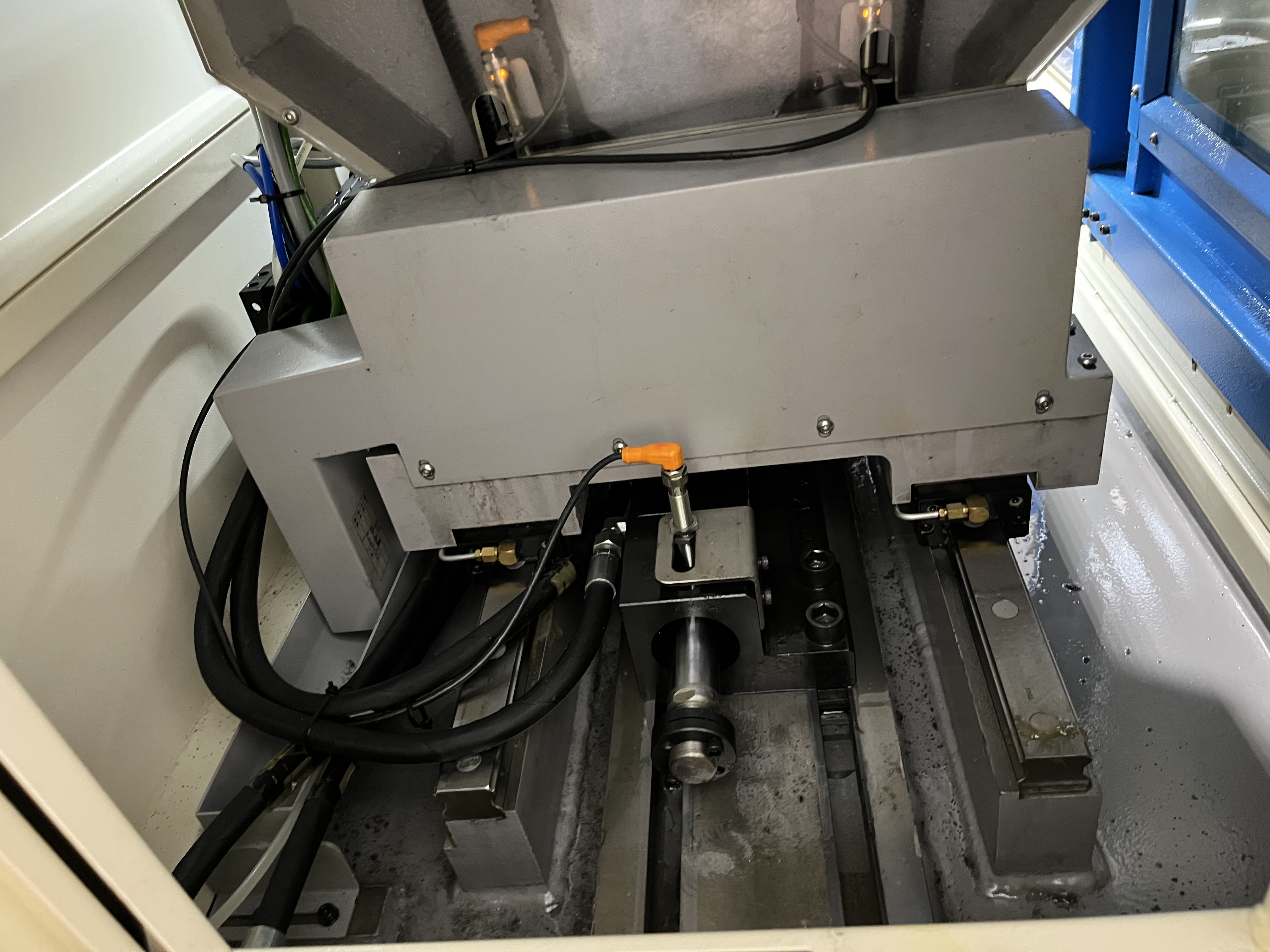
I set up ejector drilling tooling differently from gun drilling. The double-tube assembly changes everything — how coolant flows, how chips exit, and how I approach alignment.
Ejector drilling uses a double-tube tool assembly where coolant travels down the annulus between two concentric tubes and returns through the inner tube. The setup is different from both gun drilling and BTA drilling. Get it wrong, and you will scrap parts. I have scrapped enough to know where the pitfalls are.
Here is what I have learned about ejector drilling tooling after several years of running these machines.
How the Double-Tube Assembly Works
The ejector drill assembly consists of three main components that work together:
- Outer tube. Carries coolant from the machine to the cutting head. Takes the most abuse from chip abrasion over time.
- Inner tube. Carries chips and return coolant back through the drill. Diameter determines chip clearance — too small and chips jam.
- Cutting head. Mounted on the end of the outer tube. Contains the cutting inserts and guide pads. Interchangeable for different diameters and materials.
I replace the outer tube when wall thickness wears below 80% of original. Measuring it takes thirty seconds with a caliper and has saved me from at least two tube ruptures.
Coolant Flow Path
Coolant flows through the gap between the outer and inner tubes. At the cutting head, the coolant passes through the cutting zone and then enters the inner tube through the ejector nozzle.
The ejector nozzle creates a Venturi effect that draws chips into the inner tube. This is what gives ejector drilling its name. I have seen the Venturi effect stop working if the nozzle clearance drops below 0.5 mm — I check it every tool change. Once, a 0.3 mm clearance drop caused chip packing that broke a $400 cutting head in under two seconds.
Step-by-Step Setup Procedure
Here is the procedure I follow for every ejector drilling setup:
- Mount the outer tube in the machine spindle. Check runout at the tube end — keep it under 0.05 mm TIR.
- Install the inner tube inside the outer tube. Verify it slides freely without binding.
- Mount the cutting head. Torque the retaining screws to the manufacturer specification, not tighter.
- Install the ejector nozzle. Verify the clearance between nozzle and inner tube is within spec — typically 0.5–0.8 mm.
- Connect coolant lines. Check for leaks at every fitting before running the machine.
- Set coolant pressure. Start at 300 psi and adjust based on chip formation.
- Install steady rests. Support the outer tube at 500 mm intervals for holes deeper than 500 mm.
- Run a test cycle. Drill 50 mm into a scrap piece and inspect the chips before production.
I skip step 2 or 7 maybe once a year when I am in a hurry. Every single time I regret it.
Tooling Components Reference Table
| Component | Material | Replacement Criterion | Typical Life |
|---|---|---|---|
| Outer tube | Alloy steel | Wall thickness < 80% original | 500–800 hours |
| Inner tube | Hardened steel | Chip abrasion wear > 0.2 mm ID | 300–500 hours |
| Cutting head | Carbide body | Guide pad wear > 0.3 mm | 50–150 hours |
| Ejector nozzle | Hardened steel | Clearance > 0.8 mm | 200–400 hours |
| Guide pads | Carbide | Flank wear > 0.3 mm | 20–60 hours |
I track these replacement intervals in a spreadsheet. The numbers vary by material, but these are my baselines for 4140 steel.
Common Setup Mistakes I Have Made
Wrong nozzle size. Using an ejector nozzle that is too large drops the Venturi effect and chips stop flowing. Too small and back pressure spikes. I keep a nozzle sizing chart on the machine cabinet.
Insufficient outer tube support. Running without steady rests on holes past 500 mm depth guarantees whipping. Whipping ruins hole straightness and wears guide pads unevenly. One job I ran without a steady rest produced holes 0.15 mm oversize at 800 mm depth.
Incorrect guide pad selection. Using the wrong guide pad material for the workpiece causes galling. For stainless steel, I use guide pads with higher cobalt content. For aluminum, I use uncoated carbide.
Coolant contamination. Chips left in the coolant system clog the ejector nozzle mid-cycle. I check the coolant filter before every setup. A clogged nozzle mid-hole is a disaster — the drill fills with chips and seizes.
Over-torquing cutting head screws. The retaining screws strip easily. I use a torque wrench set to the manufacturer spec, never a hex key by feel.
Parameter Recommendations
| Material | Coolant Pressure (psi) | Feed (mm/rev) | Surface Speed (m/min) | Chip Expected |
|---|---|---|---|---|
| Mild steel | 250–350 | 0.08–0.15 | 60–90 | Short broken |
| 4140 alloy | 300–400 | 0.06–0.12 | 50–75 | Short broken |
| Stainless 304 | 350–450 | 0.05–0.10 | 40–60 | Fine chips |
| Aluminum | 200–300 | 0.12–0.20 | 100–150 | Small crescents |
| Cast iron | 250–350 | 0.10–0.18 | 50–70 | Powdery flake |
These are starting points. I adjust feed based on chip shape — increase feed if chips come out stringy, decrease if they come out as powder.
Why Setup Precision Matters More Than Gun Drilling
Ejector drilling is less forgiving of misalignment than gun drilling. The double-tube system has tighter clearances. A 0.1 mm runout at the spindle shows up as a 0.3 mm diameter error at 500 mm depth. I check spindle-to-workpiece alignment with a test bar before every new job.
The tooling is also more expensive. A complete ejector drilling assembly for a 25 mm hole costs roughly three times what a comparable gun drill costs. That means setup errors cost more money when they break tooling.
Key Takeaways
- The ejector nozzle clearance must stay between 0.5–0.8 mm for the Venturi effect to work properly.
- Support the outer tube with steady rests every 500 mm — whipping ruins hole quality and tool life.
- Use a torque wrench for cutting head retaining screws. Hand-tightening strips threads.
- Check coolant cleanliness before every setup. Contaminated coolant clogs the nozzle mid-hole.
- Start coolant pressure at 300 psi and adjust based on chip shape, not a fixed number.
- Track tooling component wear in a spreadsheet. Replacement on schedule prevents unplanned downtime.