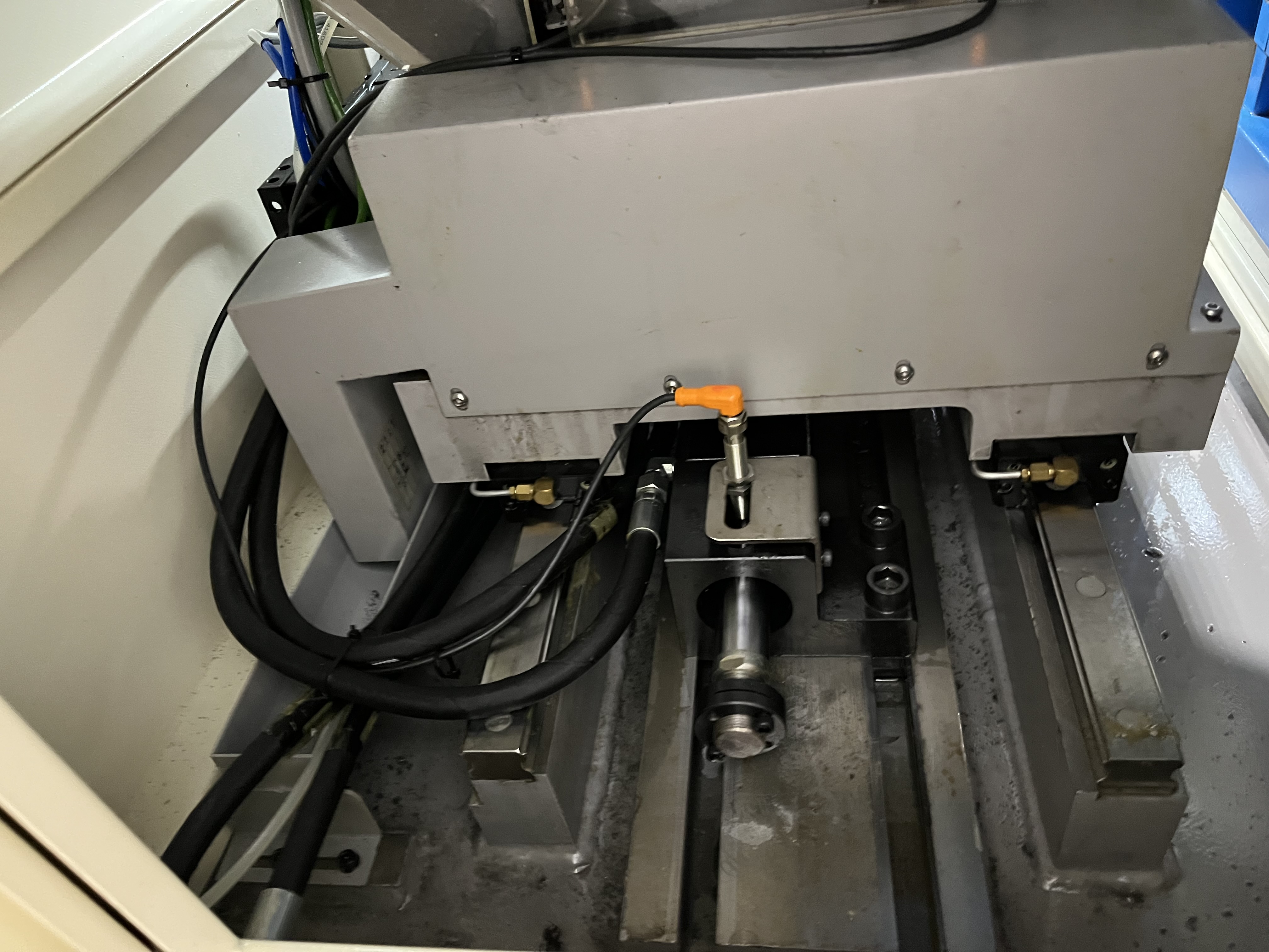
Ejector drilling uses a double-tube system where coolant flows between the outer and inner tubes and returns through the inner tube by Venturi effect. When problems happen, they are almost always related to coolant flow or nozzle condition. I have worked through enough ejector drilling issues to recognize the patterns fast. The double-tube design gives ejector drilling advantages in portability and setup simplicity, but the troubleshooting demands a different mindset than standard gun drilling or BTA drilling.
Poor Chip Evacuation
Poor chip evacuation is the most common issue in ejector drilling. The coolant flow through the ejector nozzle creates the Venturi effect that pulls chips through the inner tube. If the nozzle is worn or clogged, the Venturi effect weakens and chips do not clear the bore.
I check the nozzle first. A worn nozzle has visible erosion at the orifice — the bore diameter increases by 0.1-0.3mm over time. I measure the orifice diameter with a pin gauge and replace the nozzle when it exceeds the original diameter by 0.15mm. A new nozzle costs about $50 and takes 10 minutes to replace. Nozzle erosion accelerates when the coolant has abrasive fines, so I also check coolant filtration quality whenever I see rapid nozzle wear.
The other common cause of poor chip evacuation is low coolant flow. The Venturi effect needs a minimum flow rate to generate the pressure differential that pulls chips through. For most ejector drilling systems, the minimum flow is 30-60 L/min depending on the tube diameter. I use an inline flow meter on the supply line to verify flow before starting a production run. Anything below 35 L/min on a 20mm diameter system tells me something is restricting flow.
Expanded Problem-Cause-Fix Table
Here is the full troubleshooting table I use on the shop floor. I have added more specific issues I have encountered across different materials and setups.
| Symptom | Likely Cause | Diagnosis Check | Fix | Priority |
|---|---|---|---|---|
| Chips not returning at all | Worn ejector nozzle | Measure orifice diameter with pin gauge | Replace nozzle | Immediate |
| Chips returning slowly | Low coolant flow | Flow meter reading below 35 L/min | Clean filters, check pump output | High |
| Chips packed at start of bore | Debris lodged in nozzle | Remove and inspect nozzle bore | Clean nozzle with compressed air | High |
| Intermittent chip flow | Air entrained in coolant | Check return line for visible bubbles | Bleed system at tool head connection | Medium |
| Chips too long for tube ID | Incorrect feed rate | Measure chip length against tube ID | Reduce feed or install chip breaker | Medium |
| Chip stringers wrapping around tube | High ductility material | Visual inspection of chip form | Increase coolant flow or adjust feed | Medium |
| Fine powder chips, no flow | Worn guide pads on head | Check guide pad wear clearance | Replace guide pads | High |
| Foam in coolant return | Coolant chemistry issue | Concentration test with refractometer | Adjust concentration to 8-10% | Medium |
| Chip flow stops after 100mm depth | Blockage at tube connection | Disconnect and inspect inner tube joint | Clean joint area, check alignment | Immediate |
| Coolant returning but no chips | Drill head worn out | Inspect cutting edges for wear | Replace drill head | Immediate |
| Variable chip flow with pump sound changes | Pump cavitation from low tank level | Check coolant tank level | Top up coolant to correct level | Immediate |
| Chips coming out as powder | Feed too low causing rubbing | Compare actual feed to recommended | Increase feed to 0.03-0.06 mm/rev | Medium |
Coolant Pressure Diagnosis
I built a systematic diagnostic approach for coolant pressure issues in ejector drilling. The pressure at the tool head is the single most important variable, and it gets affected by problems all along the coolant path.
I start at the pump and work forward. First, I check the pump discharge pressure gauge. A new pump on a typical ejector drilling system should show 800-1200 psi at the pump outlet. If the discharge pressure is low, the pump is worn, the motor is underpowered, or the pump inlet is starved.
Next, I check the pressure at the machine spindle inlet. The pressure drop between the pump and the spindle should be under 50 psi. If I see a larger drop, I look for restrictions in the supply line — kinked hoses, clogged swivel joints, or partially closed valves.
Finally, I check the pressure at the tool head. This is where ejector drilling differs from other deep hole drilling processes. The tool head pressure should be 200-400 psi. If the pressure is correct at the spindle but low at the tool head, the problem is in the double-tube assembly — usually a leak at the inner tube connection or a worn ejector nozzle.
I use a pressure tap at the tool head connection for accurate readings. Without that measurement, I am guessing at the real pressure at the cutting zone. I retrofitted pressure taps on all my ejector drilling machines after chasing a phantom chattering problem for three days that turned out to be a 150 psi drop across a worn nozzle.
Tool Wear Patterns in Ejector Drilling
Tool wear in ejector drilling follows different patterns than gun drilling because of the chip evacuation method. The chips pass through the center of the tool, so the wear on the inner cutting edge differs from the outer edge.
I have observed four distinct wear patterns on ejector drilling heads. Normal wear shows uniform flank wear across all cutting edges with no chipping. I replace the head when flank wear reaches 0.3mm on any cutting edge.
Abnormal wear pattern one is edge chipping. This happens when interrupted cuts or hard inclusions in the material hit the cutting edge. I spot it by the irregular loss of cutting edge material. The fix is to check material consistency and reduce feed rate by 20% during entry.
Pattern two is crater wear on the rake face. This indicates the cutting temperature is too high. I see this when running at high speeds with insufficient coolant flow. Reducing cutting speed by 15% usually resolves it.
Pattern three is notch wear at the depth of cut line. This happens when the surface of the workpiece has a hard layer — scale, case hardening, or work hardening from a previous operation. I machine off the hard layer before drilling or use a tougher carbide grade.
For more on tool selection, see the BTA drilling explained guide.
Tube Wear Inspection and Replacement
The drill tube wears on the OD where it contacts the steady rests. The steady rests support the tube every 300-500mm along its length. The contact points wear the tube OD over time, especially at high spindle speeds. I have seen tubes develop flat spots at the steady rest contact points after 2000 hours of operation.
I inspect the tube OD with a micrometer at each steady rest location monthly. I replace the tube when the OD wear exceeds 0.5mm at any point. A worn tube can collapse under coolant pressure — the wall thickness is reduced and the tube loses hoop strength. I had a tube collapse at 600 psi on a machine once, and it took two days to extract the broken pieces from the bore.
The inner tube also wears at the connection points. The inner tube carries the chips and coolant return flow. If the inner tube connection leaks, coolant recirculates without reaching the cutting zone. I pressure-test the inner tube assembly annually by blocking the tool end and pressurizing to 300 psi. Any pressure drop of more than 50 psi over 10 minutes means a seal or connection needs attention.
For more on drill tube maintenance, see the drill tube selection guide.
Coolant System Blockages and Preventive Maintenance
Nozzle blockage happens when debris in the coolant system lodges in the nozzle opening. The nozzle orifice is small — typically 3-8mm diameter — and any particle larger than the orifice gets stuck. I clean the coolant filters more frequently on ejector drilling machines to prevent this.
I change the filter elements every 40 hours of runtime on ejector drilling machines, compared to 80 hours on standard gun drilling. The tighter clearances in the double-tube system make it more sensitive to debris. A single particle lodged in the nozzle can stop production for an hour while I disassemble and clean.
I also flush the coolant system before switching between materials. Residual chips from a steel job can lodge in the nozzle when I switch to aluminum. A system flush with clean coolant takes 30 minutes and prevents nozzle blockages. I have a dedicated flushing procedure that runs coolant through the system without the drill tube installed to clear any settled debris.
For more on coolant system care, see the coolant leak detection and repair guide.
Key Takeaways
- Check the ejector nozzle first for chip evacuation problems — it wears and needs replacement every 6-12 months depending on coolant cleanliness.
- Ejector drilling needs 200-400 psi at the tool head — lower pressure causes chattering and poor chip flow.
- Use the full 12-row problem-cause-fix table to systematically diagnose chip evacuation issues by priority level.
- Change coolant filters every 40 hours on ejector drilling machines, twice as often as standard gun drilling.
- Inspect tube OD at steady rest contact points monthly and replace when wear exceeds 0.5mm.
- Flush the coolant system between material changes to prevent nozzle blockages from residual chips.
- Monitor coolant pressure at three points — pump discharge, spindle inlet, and tool head — to isolate restrictions quickly.
- Recognize the four tool wear patterns in ejector drilling: normal flank wear, edge chipping, crater wear, and notch wear.