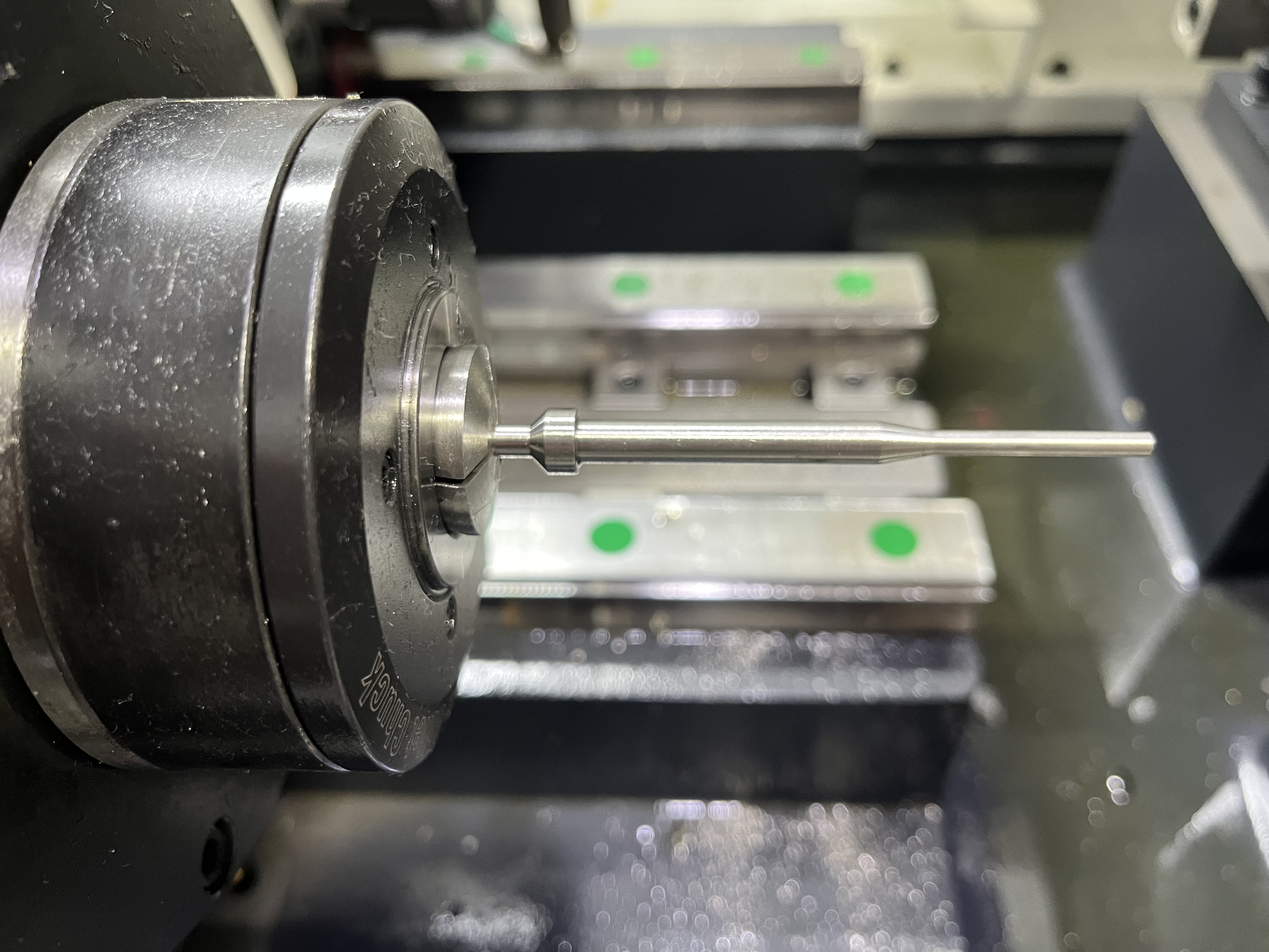
A first article inspection verifies that the drilling process produces parts within specification before production begins. I run a first article inspection on every new job before approving the batch for production. The inspection catches setup errors, tool problems, and parameter issues before they multiply across hundreds of parts.
The Five Measurements I Always Take
My first article inspection covers five critical dimensions and characteristics:
- Hole diameter at entry, mid-length, and exit
- Surface finish at entry and exit
- Hole straightness over the full length
- Hole position relative to datum features
- Wall thickness concentricity
I record every measurement on a checklist that stays with the first article part until the inspection is complete. If any measurement is out of spec, the part is tagged and quarantined for review.
Diameter Measurement Procedure
For the hole diameter, I measure at three locations along the bore with a two-point bore gauge:
| Measurement Location | Purpose | Typical Variation |
|---|---|---|
| Entry (10 percent of depth) | Detects guide bushing wear or misalignment | 0.005-0.015 mm over drill size |
| Mid-length (50 percent of depth) | Shows general process stability | 0.005-0.020 mm over drill size |
| Exit (90 percent of depth) | Detects tool deflection or drill wear | 0.005-0.025 mm over drill size |
The diameter should be consistent within 0.02 mm over the length. A larger diameter at the entry than at the exit indicates the guide bushing is worn or the drill is deflecting at the start. A larger diameter at the exit indicates the drill is wandering as it exits the part.
I use a bore gauge with 0.001 mm resolution for diameter measurement. For holes under 6 mm diameter, I use an air gauge because the bore gauge cannot fit in the small bore.
Surface Finish Measurement
I measure surface finish with a profilometer at the entry and exit locations. The finish should meet the print specification at both locations.
| Location | Typical Gun Drilled Ra | What Deviation Indicates |
|---|---|---|
| Entry | 0.4-0.8 um | Bushing condition, entry support |
| Mid-length | 0.5-1.0 um | Coolant pressure, chip evacuation |
| Exit | 0.4-0.8 um | Tool wear, material condition |
A rougher finish at depth compared to the entry indicates inadequate coolant pressure or tool wear. The finish at the exit should be similar to the entry finish if the process is stable. A big jump between entry and exit Ra values triggers a coolant pressure check.
Straightness Measurement
Straightness is the hardest measurement to make on a deep hole, but it is also the most critical for hydraulic and structural applications. I use two methods depending on the part length:
| Part Length | Measurement Method | Accuracy |
|---|---|---|
| Under 500 mm | CMM touch probe | +/- 0.005 mm |
| 500-1,500 mm | Test bar in bore + dial indicator | +/- 0.01 mm |
| Over 1,500 mm | Laser bore measurement system | +/- 0.02 mm |
For the test bar method, I insert a precision ground bar that fits the bore diameter within 0.01 mm. The bar extends from the bore and I sweep a dial indicator along the bar to measure the deviation.
Straightness should be within the print tolerance over the full length. A curved hole that is within tolerance can still be acceptable for many applications. I have seen hydraulic cylinders with 0.05 mm bow over 1 meter operate perfectly for years.
Position and Wall Thickness Checks
The hole position relative to the part datum features must be checked. I measure the position with a CMM using the same datum references the part will use in assembly.
Position tolerance for deep holes is typically 0.1-0.2 mm of the design coordinate. If the hole position is off, the issue is usually the workpiece setup rather than the drilling process.
Wall thickness concentricity matters when the finished part needs uniform material thickness around the bore. I measure wall thickness at four points around the circumference at the entry and exit. A wall thickness variation of more than 0.1 mm indicates the workpiece was not centered when drilled.
First Article Documentation
Every measurement goes onto a first article inspection report that includes:
- Part number and revision
- Date and operator name
- Machine ID
- Tool description and serial number
- Drilling parameters used
- All measured values with pass/fail indicators
- Inspector name and approval signature
The report stays on file for the customer and for internal quality records. I have used first article reports to diagnose process drift months later by comparing them to current inspection results.
Corrective Action When First Article Fails
If any check fails, I adjust the process and run another first article before starting production. The corrective action depends on the failure:
| Failure Mode | Likely Cause | Corrective Action |
|---|---|---|
| Oversize diameter entry | Worn guide bushing | Replace bushing |
| Oversize diameter exit | Tool deflection | Increase feed or reduce speed |
| Rough finish at depth | Low coolant pressure | Check pump, filters, rotating union |
| Poor straightness | Machine misalignment | Realign spindle to bushing |
| Position error | Workpiece setup | Reposition and reclamp |
I do not start production until the first article passes all checks. The time spent on a first article inspection is trivial compared to the cost of scrapping a batch of production parts.
Key Takeaways
The first article inspection is the most important quality check in deep hole drilling. The five-part check of diameter, surface finish, straightness, position, and wall thickness catches problems before they become scrap. The documentation provides a baseline for future troubleshooting and quality audits. I treat the first article as a process validation, not just a part inspection, and I do not start production without a passing first article.