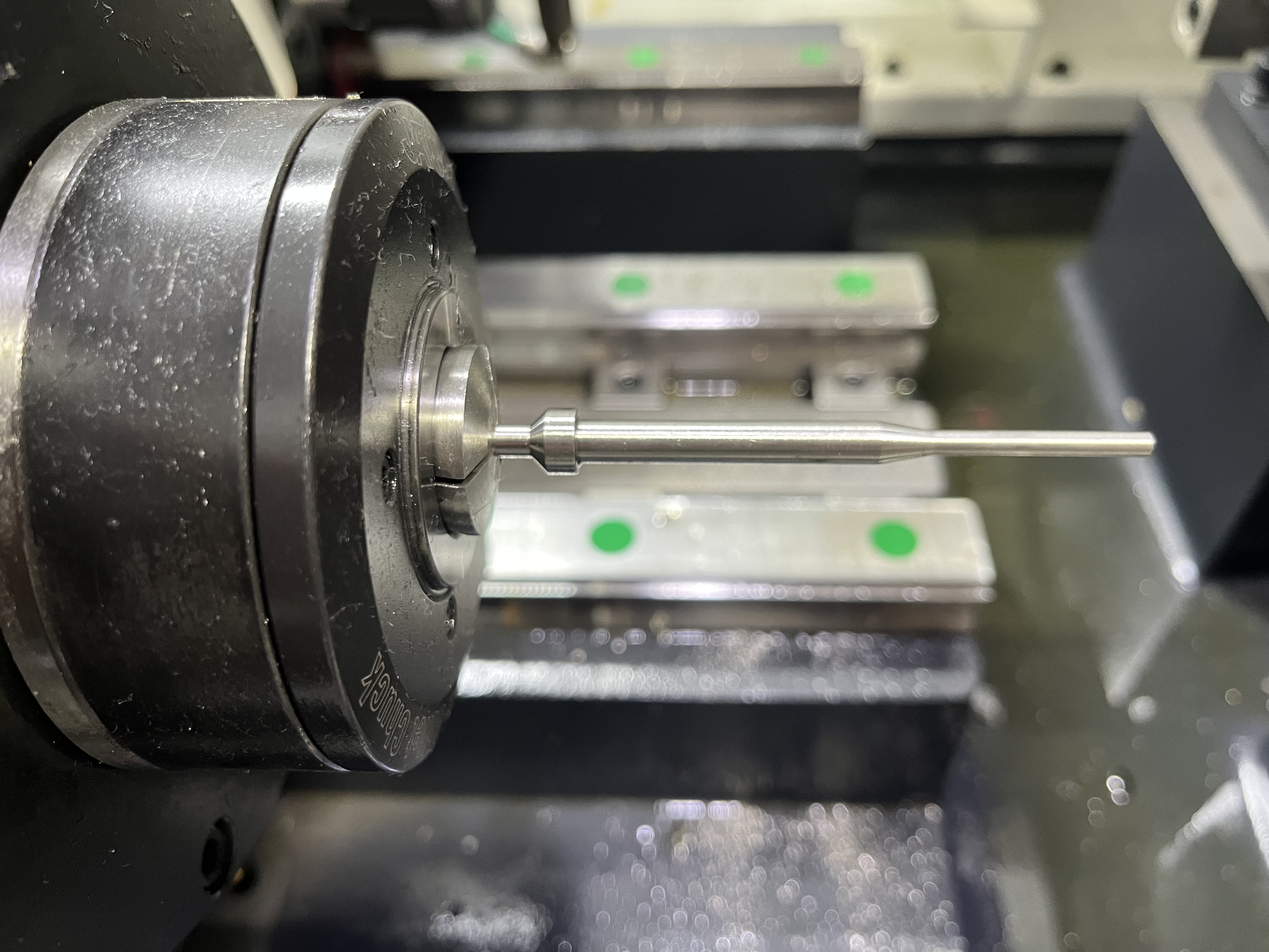
Gun Drill Entry Bushings: Selection, Clearance, and What I’ve Learned About Getting the Start Right
I have been working with gun drilling systems for long enough to know where the real problems hide. After years of chasing burrs, wander marks, and scrapped parts, I can tell you this: the entry bushing gets blamed for nothing and causes everything. I have traced more straightness problems to a worn or mismatched bushing than to anything else on the machine — coolant pressure, spindle alignment, even drill geometry all get more attention, but the humble bushing at the start of the hole is where the cut is won or lost. This article covers what I have learned about choosing, fitting, inspecting, and maintaining them so you stop fighting the first few millimeters of every hole.
What Entry Bushings Actually Do
An entry bushing looks simple — a hardened ring with a precise bore that the drill passes through before it touches the workpiece. But that ring carries three distinct responsibilities that make or break a hole before the cut even starts.
Support. The gun drill is a long, slender tool with a single cutting edge. The instant it contacts the workpiece, unbalanced radial forces try to push it off course. The entry bushing is the only rigid support close to the cut. It constrains the drill body at the start of engagement and prevents initial deflection. Without that support, the drill walks — and once it walks, you cannot pull it back on track.
Seal. High-pressure coolant (typically 70–120 bar in the systems I work with) is pumped through the drill’s internal passage, exits at the cutting tip, and flushes chips back along the flute. The annular gap between the drill OD and the bushing ID acts as a pressure seal. If the clearance is too large, coolant pressure drops, chip evacuation suffers, and the cutting edge runs hot. If it is too tight, the drill binds and you get a friction-burn on the bushing wall within seconds.
Alignment. The bushing establishes the drill’s entry angle relative to the workpiece surface. Even a 0.01 mm misalignment in the bushing holder translates to measurable axis deviation at depth. I always check bushing concentricity with a tenths-indicator before I run a new setup — the time spent there saves hours of scrapped parts downstream.
Bushing Materials: Carbide vs. Steel vs. Ceramic
The material you choose for the entry bushing directly affects tool life, part quality, and how often you stand at the machine changing bushings. Here is how the three common options stack up in practice.
| Material | Wear Life | Relative Cost | Best Application |
|---|---|---|---|
| Carbide (sintered tungsten) | 15,000–30,000 holes (typical) | 3–5x steel | Production runs, abrasive materials (cast iron, composites), tight-tolerance holes |
| Tool Steel (D2, M2, A2, through-hardened) | 3,000–8,000 holes | 1x (baseline) | Short runs, soft steels, aluminum, prototype work, low-volume job shops |
| Ceramic (silicon nitride, zirconia) | 30,000–60,000 holes | 8–12x steel | High-speed production, dry or near-dry drilling, hardened steels, chemical corrosion environments |
I keep carbide bushings in my primary holders for production work and swap in steel bushings for quick-turn prototypes. Ceramic is impressive on paper but the brittleness worries me in shops where operators bump tooling during changeovers — one chip in the bore edge and the bushing is scrap.
One more thing on material: the bushing bore finish matters as much as the base material. A ground ID with Ra 0.2 or better reduces friction and improves coolant sealing regardless of whether you pick carbide or steel.
Clearance Selection by Diameter and Tolerance
The radial clearance between the gun drill OD and the bushing ID is the single most important dimension on the bushing. Too loose and the drill wanders; too tight and it seizes. The table below is the starting point I use, based on standard drill tolerances (h6 or h7 shank) and typical production conditions.
| Drill Diameter (mm) | Recommended Bushing ID Clearance (mm) | Notes |
|---|---|---|
| 2.0 – 4.0 | 0.004 – 0.008 | Tight clearance critical; small drills are stiffness-limited |
| 4.0 – 8.0 | 0.006 – 0.012 | Watch coolant flow — narrow range balances seal vs. friction |
| 8.0 – 15.0 | 0.008 – 0.015 | Most common production range; confirm with temperature rise test |
| 15.0 – 25.0 | 0.010 – 0.020 | Larger drills tolerate more clearance; seal becomes the limiter |
| 25.0 – 40.0 | 0.015 – 0.025 | High-volume coolant needed; bushing wear accelerates at larger IDs |
These numbers assume a sharp drill and steady-state temperature. If you run high RPM with small diameters, thermal expansion can close the clearance gap mid-cycle. I have learned the hard way to add 0.002 mm to the low end of the range for stainless steels and other materials with poor thermal conductivity.
For tight-tolerance work (hole tolerance within ±0.025 mm), I fit each bushing to the specific drill shank rather than relying on nominal diameters. A tenths mike and a few extra bushings in the drawer pays for itself fast.
Wear Inspection and Replacement Intervals
Entry bushings wear, and they wear faster than most people expect. The telltale signs are visible if you know where to look.
I inspect bushings at every tool change or every 500 holes, whichever comes first. The inspection is straightforward:
- Visual check under 5–10x magnification for scoring, galling, or a polished wear band at the exit face.
- Go / No-Go pin check with a plug gage 0.005 mm over the original ID. If the pin passes, the bushing is worn.
- ID measurement with a bore gage at three depths (entry face, midpoint, exit face). Uneven wear means the bushing holder or spindle alignment needs attention.
I replace carbide bushings when the ID has grown 0.008 mm beyond the original spec for diameters under 10 mm, and 0.015 mm for larger diameters. Steel bushings get replaced sooner — at 0.005 mm growth for small diameters — because steel wears faster and the bore degrades non-uniformly.
For critical holes (hydraulic spools, fuel injector bodies, medical implants) I replace bushings at fixed intervals regardless of measured condition. Interval length depends on material being drilled: 8,000 holes in aluminum, 3,000 in 4140 steel, 1,500 in titanium. This prophylactic approach is expensive, but the cost of a single out-of-spec scrapped part is higher.
If you notice a pattern of bore oversize on the entry side only, check the bushing holder for perpendicularity. I have fixed more than one straightness problem by re-shimming the holder rather than swapping the bushing.
Common Bushing-Related Problems (And What They Tell You)
Over the years I have learned to read bushing wear patterns like a diagnostic tool. Here are the most common failure modes and what each one points to.
Bell-mouthed entry (wider at the front face). The bushing is misaligned with the drill axis, or the workpiece surface is angled relative to the spindle. Check your holder squareness and workpiece clamping.
Scoring or galling on the bore wall. Insufficient clearance, inadequate lubrication, or a dull drill pushing excess thrust through the bushing. Reduce clearance or increase coolant concentration.
Polished band at the exit face only. The drill is contacting the bushing at the rear during retraction — usually a retraction-speed or chip-packing issue. Clean the flute program and check chip shape.
Oval wear (ID measures different in X vs. Y). The bushing holder is distorted from over-torqued set screws, or the machine spindle has a concentricity problem. Pull the holder and indicate it on a surface plate.
Rapid, uniform bore enlargement. Abrasive workpiece material (high-silicon aluminum, cast iron with sand inclusions, carbon-fiber composites). Switch to carbide or ceramic, and consider a compressed-air purge to keep abrasive chips from recirculating through the bushing.
Each of these patterns has saved me hours of blind troubleshooting. I discuss a related problem — material transfer to the bushing wall — in more detail in my article on material transfer in guide bushings, and for a broader look at bushing role in the overall machine setup, see guide bushings in deep hole drilling.
Bushing Lubrication
Lubrication at the entry bushing is different from coolant-through-the-drill lubrication. The bushing bore needs a thin hydrodynamic film between the drill OD and the bushing ID. Without it, microwelding occurs on the bore surface within the first few revolutions.
I run a dedicated oil-mist or drip-feed lubrication line to the bushing holder on machines that see more than one shift per day. Straight cutting oil at the bushing entry works best — water-miscible coolants evaporate too quickly and leave the bore dry at high RPM. When I cannot plumb a separate line, I increase the coolant-through-the-drill pressure enough to create a backflow at the bushing exit that wets the bore continuously. This is less effective but acceptable for short runs.
For ceramic bushings, lubrication is even more critical. Ceramic’s higher hardness does not reduce friction — in fact, the coefficient of friction between ceramic and tool steel is higher than steel-on-steel. I always run ceramic bushings with a sulfurized or EP-additive oil to prevent the boundary-layer breakdown that chips the bore edge.
If the bushing runs dry, you will see smoke within 10 seconds at typical gun drilling RPM. That smoke means the bushing bore surface is degrading and needs immediate replacement — not re-lapping, not cleaning — replacement.
Key Takeaways
- The entry bushing does triple duty: it supports the drill against deflection, seals high-pressure coolant, and establishes hole entry alignment. Do not treat it as a passive component.
- Carbide bushings are the workhorse for production; steel bushings are fine for prototypes and short runs; ceramic lasts longest but is brittle and needs good lubrication discipline.
- Radial clearance between drill and bushing ranges from 0.004 mm for small diameters up to 0.025 mm for large diameters. Measure, do not guess.
- Inspect bushings every 500 holes or at every tool change. Replace at 0.008–0.015 mm bore growth depending on diameter. For critical work, swap on a fixed schedule.
- Read wear patterns to diagnose machine problems — bell-mouthing, oval wear, and polished bands each tell a different story about alignment, lubrication, or chip evacuation.
- Lubricate the bushing bore separately from the drill coolant, especially at high RPM and with ceramic bushings. Dry-running a bushing destroys it in seconds.
- A tenths indicator, a bore gage, and a spare bushing in the drawer solve more gun drilling problems than any software parameter I have ever adjusted.