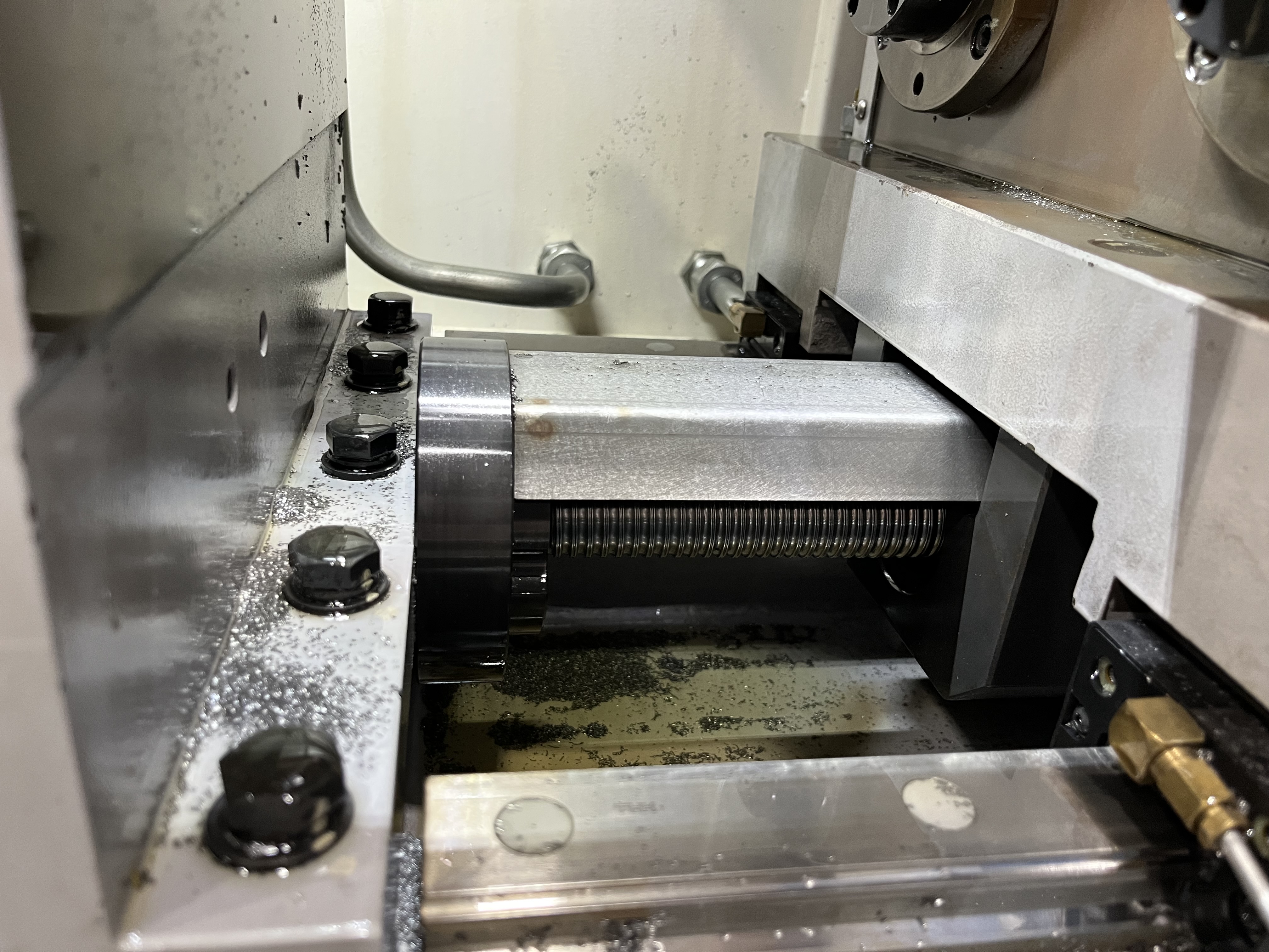
I have been running gun drills for over a decade, and the single biggest productivity gain I ever made was laminating a reference card and taping it to every machine I run. When the spindle is stopped and chips need clearing, I don’t want to dig through a binder or scroll through a PDF. I want the number, right there. This article is that card, blown up with the context and edge-case notes that never fit on the laminated sheet.
If you are new to setting up gun drilling parameters, I recommend first reading my overview on deep hole drilling parameters and the practical guide on how to set deep hole drilling parameters. Those two articles walk through the fundamental formulas and the logic behind starting point selection.
How to Use the Reference Tables
The tables below give starting parameters for carbide-tipped gun drills with standard geometry (30-degree point angle, single-lip design) running on rigid machines with high-pressure coolant systems. Every value assumes adequate coolant filtration to 20 microns or better and a pilot hole or bushing at entry.
Here is my rule of thumb: start at the low end of the recommended speed range and the middle of the feed range. Listen to the cut. If the chips come out as fine, consistent flakes and the coolant pressure gauge stays steady, bump speed by 10%. If the drill starts chattering before you reach 80% of the expected tool life, drop speed by 15% on the next part and work back up.
All values assume flood coolant applied through the drill shank at the listed pressure. Never reduce coolant pressure to compensate for chatter — that is almost always a chip evacuation problem, and lowering pressure makes it worse.
Speed and Feed Recommendations by Material
These values are for gun drills in the 6 mm to 12 mm diameter range. Apply the diameter adjustment factors from the next section when drilling smaller or larger holes. Tool life is based on regrindable carbide-tipped drills; solid carbide gun drills will typically show 20-30% shorter life before requiring replacement.
| Material | Speed (SFM) | Feed (IPR) | Coolant Pressure (PSI) | Expected Tool Life (m) |
|---|---|---|---|---|
| Low-carbon steel (1018) | 250-350 | 0.0010-0.0018 | 800-1200 | 25-40 |
| Medium-carbon steel (1045) | 200-300 | 0.0008-0.0015 | 1000-1500 | 20-35 |
| Alloy steel 4140 (annealed) | 180-260 | 0.0008-0.0012 | 1200-1800 | 15-25 |
| Tool steel D2 (annealed) | 80-120 | 0.0005-0.0008 | 1500-2000 | 8-15 |
| Stainless steel 304 | 140-200 | 0.0006-0.0010 | 1300-1800 | 10-18 |
| Stainless steel 17-4 (H900) | 120-180 | 0.0006-0.0009 | 1500-2000 | 10-15 |
| Aluminum 6061 | 400-600 | 0.0015-0.0030 | 400-800 | 80-120 |
| Aluminum 7075 | 350-500 | 0.0012-0.0025 | 500-900 | 60-100 |
| Titanium 6Al-4V | 80-120 | 0.0005-0.0008 | 1800-2500 | 8-15 |
| Inconel 718 (annealed) | 40-70 | 0.0004-0.0007 | 2000-3000 | 5-10 |
| Cast iron (gray) | 200-350 | 0.0012-0.0020 | 600-1000 | 25-40 |
| Cast iron (ductile) | 160-250 | 0.0010-0.0016 | 800-1200 | 20-30 |
| Brass (free-machining) | 400-600 | 0.0015-0.0030 | 300-600 | 60-100 |
| Copper (pure, C110) | 200-300 | 0.0010-0.0020 | 600-900 | 20-35 |
| Magnesium AZ31 | 500-800 | 0.0015-0.0035 | 300-500 | 100-150 |
| Plastics (nylon, acetal) | 300-500 | 0.0010-0.0020 | 200-400 | 50-80 |
Notes on specific materials:
Low-carbon steel (1018) — This is the most forgiving material I run. Chips break easily, tool life is long, and coolant pressure can sit at the low end. The upper feed range works well when you need penetration rate; just watch for built-up edge if you push speed past 350 SFM.
Alloy steel 4140 — Annealed 4140 needs the higher coolant pressure to clear the stringy chips it wants to produce. If I see chip packing, I increase pressure before I reduce feed. Pre-hardened 4140 (28-32 HRC) should be run 20% slower on speed and 15% lower on feed.
Stainless steel 304 — Work hardening is the enemy here. Once the drill enters the cut, do not stop the feed. Every pause creates a work-hardened ring that shortens tool life dramatically. If you must dwell, retract the drill first.
Aluminum 6061 — I push the speed as high as the machine allows. The limiting factor is almost never tool wear; it is maintaining enough coolant pressure to clear chips from a deep hole. Drop feed before dropping speed when chips are not clearing.
Titanium 6Al-4V — Titanium is unforgiving. The chip thinning effect at high feed will catch you off guard. I prefer the lower end of the feed range and coolant pressure at 2000 PSI or more. If the drill squeals, back the feed off, not the speed.
Inconel 718 — Expect short tool life and plan regrinds accordingly. Every extra 500 PSI of coolant pressure buys you measurable meters of hole. I have run these as low as 35 SFM in tough sections with acceptable results.
Plastics — The risk is melting, not tool wear. Keep coolant pressure moderate to avoid lifting uncut fibers in glass-filled grades. Unfilled acetal and nylon drill beautifully at 400 SFM with 0.0015 IPR.
Coolant Pressure Recommendations by Material and Diameter
Coolant pressure in gun drilling serves two jobs: lubricating the cut and pushing chips out the flute. Small diameters need higher pressure because the chip-escape annulus is smaller. The table below gives minimum recommended pressures.
| Drill Diameter | Steels (PSI) | Stainless (PSI) | Aluminum (PSI) | Titanium / Inconel (PSI) |
|---|---|---|---|---|
| 3-5 mm | 1500-2000 | 1800-2500 | 800-1200 | 2500-3000 |
| 6-12 mm | 1000-1500 | 1300-1800 | 400-800 | 1800-2500 |
| 13-20 mm | 700-1000 | 900-1300 | 300-500 | 1200-1800 |
| 21-30 mm | 500-800 | 700-1000 | 200-400 | 800-1200 |
| 30+ mm | 400-600 | 500-800 | 150-300 | 600-900 |
Pressure matters more than flow rate for chip evacuation. If your machine cannot reach the listed pressure for a given diameter and material combination, reduce feed rather than speed to keep the chip load manageable.
How to Adjust for Diameter (Scaling Rules)
The material table above is calibrated for the 6-12 mm range. Here are the scaling factors I apply for other diameters:
| Drill Diameter | Speed Multiplier | Feed Multiplier |
|---|---|---|
| 1-2 mm | 0.60 | 0.50 |
| 3-5 mm | 0.80 | 0.70 |
| 6-12 mm | 1.00 (baseline) | 1.00 (baseline) |
| 13-20 mm | 1.10 | 1.20 |
| 21-30 mm | 1.20 | 1.35 |
| 30+ mm | 1.30 | 1.50 |
Why the factors increase with diameter: A larger drill has a bigger coolant annulus, so chip evacuation is easier. The cutting edge also has more mass to absorb heat, and the surface speed at the outer corner climbs relative to the center. I can run a 25 mm gun drill at higher feed per revolution than a 6 mm drill because the chip is thicker relative to the edge radius, which improves cutting action and reduces rubbing.
These multipliers apply to both speed and feed independently. For a 20 mm gun drill in 4140: baseline speed is 220 SFM, multiply by 1.10 to get 242 SFM. Baseline feed is 0.0010 IPR, multiply by 1.20 to get 0.0012 IPR.
Safety Factors for First-Off Parts
When I am running a material-drill combination for the first time on a new setup, I apply a safety factor to protect against the variables I haven’t discovered yet:
- Reduce speed by 25% from the table recommendation for the first three holes. Watch for chatter, listen for squeal, and inspect the first 25 mm of the hole for surface finish.
- Keep feed at the table value. I never reduce feed on a first-off unless the material is known to work-harden easily. Light feeds with a gun drill cause rubbing, not cutting, and rubbing wears the carbide edge fast.
- Set coolant pressure 10% above the table minimum. If chips clear cleanly, I dial it back to the target pressure. Starting high and dropping is safer than starting low and discovering chip packing at 50 mm depth.
- Inspect the drill tip after the first hole. Look for micro-chipping on the outer corner and any discoloration near the carbide-brazed joint. Discoloration means the cut is running hot, and I need to reduce speed before running production.
- Run the first part at 50% of expected depth. Cut, retract, inspect. If everything looks good, run to full depth. If the gun drill deviates or the finish degrades past 50% depth, the fault is usually coolant pressure or chip packing, not the base parameters.
I keep a log of every first-off run: starting parameters, what I changed, and why. Over time this log becomes more useful than any published table, because it captures the specific quirks of each machine, holder, and coolant system combination.
When to Deviate from the Table
The table is a starting point. Here are the situations where I routinely go outside the recommended ranges:
Long length-to-diameter ratios (over 50:1). At high L:D ratios, the drill beam becomes the weakest link. Reduce both speed and feed by 15-20% from the table values and increase coolant pressure by 20%. The extra pressure helps overcome the friction of pushing chips through a longer flute.
Interrupted cuts (cross holes, keyways, splines). Drop speed by 30% and feed by 20%. Use a bushing that supports the drill as close to the interruption as possible. The moment the cutting edge hits the gap, the load spikes. A lower speed reduces the impact energy.
Worn or reground drills. I reduce speed by 15% on the first run after a regrind and inspect the hole finish. Reground drills often have slightly different edge geometry than the original, and the coolant hole position may shift. If the finish matches the original, I bring speed back up on the next part.
High-volume production. Once I have validated a setup over 50+ holes, I push speed and feed 10-15% above the table range and monitor tool wear closely. The table represents safe starting points, not optimization targets. Production validates higher parameters — but only when every variable (material lot, coolant mix, bushing wear) is controlled.
Soft or gummy materials (pure copper, low-carbon steel in thin sections). These produce long, stringy chips that can wrap around the drill or pack in the flute. I increase feed to the upper end of the range to promote chip breaking, even if it means accepting a slightly rougher surface finish. A plugged gun drill is a broken gun drill.
Machine limitations. If your machine cannot reach the recommended coolant pressure, reduce feed first. If spindle power is the limit, reduce speed. Know which constraint hits first on your setup — I have one machine where the coolant pump maxes out at 1500 PSI, and I plan all stainless steel jobs assuming I will drop feed by 20% to compensate.
Key Takeaways
- Start at the low end of speed and the middle of feed for any new material-drill combination. Listen to the cut before optimizing.
- Coolant pressure is non-negotiable. Match it to both the material and the drill diameter — small drills need higher pressure regardless of material.
- Apply diameter adjustment multipliers when deviating from the 6-12 mm baseline. Larger drills tolerate higher feed per revolution; smaller drills need reduced parameters.
- First-off safety factors protect against unknown variables: reduce speed 25%, keep feed at the table value, and set coolant pressure 10% above minimum.
- Deviate from the table intentionally. Long L:D ratios, interrupted cuts, reground drills, and production optimization all justify changes — but change one variable at a time and verify.
- Keep a log. Your own machine-specific data will outperform any published reference once you have fifty entries in it.
- Temperature is the distilled coolant pressure; listen to chatter; and never trust a number that came from a table you didn’t validate on your own spindle.