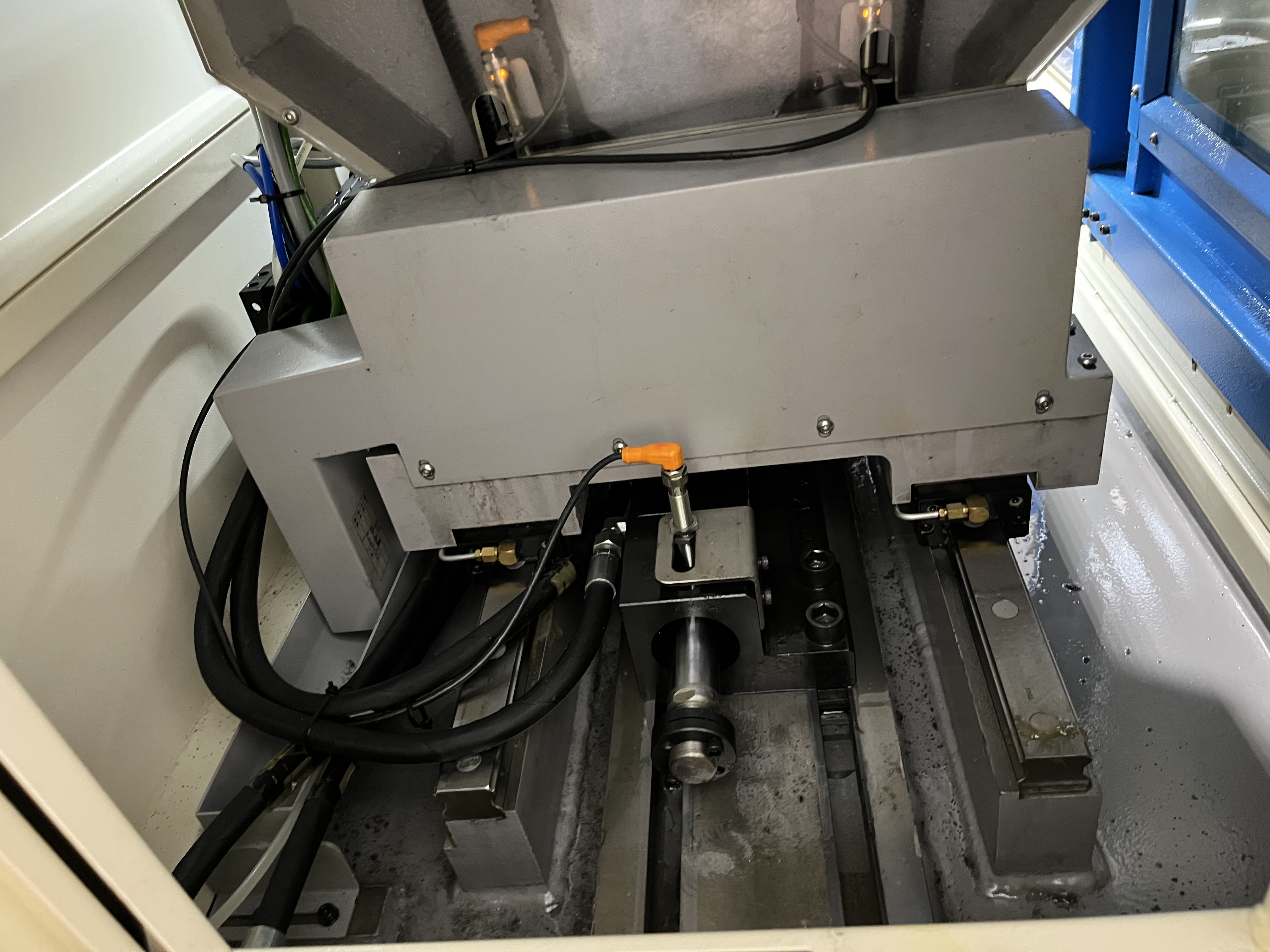
I have spent the better part of my career watching shops try to force job-shop workflows into production environments, and it almost never ends well. High-volume deep hole drilling is not just job-shop work done faster. The entire process architecture changes. When you are running thousands of parts a month instead of a handful of prototypes, every minute of downtime, every inconsistent tool change, every coolant fluctuation multiplies into real cost. Over the last decade, I have designed, tuned, and occasionally had to rescue production cells across automotive, hydraulic component, and aerospace fastener lines. Here is what I have learned about making deep hole drilling work at volume.
Production Cell Layout Options
The first and most consequential decision is whether you run a single-machine cell or a multi-machine cell. I have seen both fail and both succeed, but they succeed under very different conditions.
Single-machine cells work well when your part family is narrow, your cycle time is under ninety seconds, and your changeover frequency is low. A single machine with an integrated gantry loader, a coolant through-feed system sized for that one spindle, and a part conveyor can produce reliably at volumes up to about 80,000 parts per year on a two-shift schedule. The advantage is simplicity: one operator can manage two or three such cells, and troubleshooting is straightforward because every variable originates from one source.
Multi-machine cells become necessary when you need redundancy, mix multiple part numbers, or push above 150,000 parts per year. I typically lay these out in a U-shaped configuration with a central robot or gantry serving four to six spindles. Each machine runs a dedicated tool setup so changeover between part numbers happens at the cell level, not the machine level. The coolant and filtration system is centralized, which brings both cost savings and complexity – more on that below.
Here is the rough guide I use when recommending a configuration:
| Annual Volume | Part Family Count | Recommended Configuration | Reasoning |
|---|---|---|---|
| Under 50,000 | 1-2 | Single-machine cell | Minimal capital, one operator can oversee multiple cells |
| 50,000 - 150,000 | 2-5 | Two-machine cell with shared gantry | Balance of redundancy and utilization |
| 150,000 - 400,000 | 3-8 | Multi-machine U-cell (4-6 spindles) | Central robot loading, centralized coolant, one operator |
| Over 400,000 | 5+ | Multiple U-cells or transfer line | Dedicated lines per part family, minimal changeover |
I lean toward the two-machine cell more often than people expect. It gives you a production safety net – if one spindle goes down, you are still running at 50 percent – while keeping the coolant and automation complexity manageable.
Tool Change Strategy
In job-shop deep hole drilling, you change tools when the surface finish degrades or the drill breaks. In production, that approach will cost you a fortune in scrap and unplanned downtime. You need a predictive tool change strategy.
Preset tooling is non-negotiable at volume. Every drill should arrive at the machine with diameter, runout, and length already verified in a presetter. I have measured the time savings myself: an in-machine tool touch-off takes about forty-five seconds per tool; a presetter outside the machine takes fifteen seconds and does not consume spindle uptime. Over a 100,000-part run with three tool changes per part, that difference alone saves over 2,500 minutes of cycle time.
Tool life management requires real data, not guesses. I track drills by serial number and log spindle-on time per drill. When we start a new production run, we run tool life validation for the first 500 parts at full production parameters, measuring edge wear at fixed intervals. The result is a tool change interval that we can bank on.
Here is a simplified version of the calculation table I use:
| Tool Diameter (mm) | Material | Cutting Speed (m/min) | Tool Life (minutes) | Parts per Tool | Change Interval (parts) | Safety Factor |
|---|---|---|---|---|---|---|
| 6 - 10 | 4140 steel (28-32 HRC) | 60 - 75 | 90 - 120 | 180 - 300 | 150 | 0.8 |
| 10 - 18 | 4140 steel (28-32 HRC) | 55 - 70 | 120 - 180 | 200 - 400 | 160 | 0.8 |
| 6 - 10 | Aluminum 6061 | 120 - 150 | 200 - 300 | 500 - 800 | 400 | 0.7 |
| 10 - 18 | Aluminum 6061 | 110 - 140 | 250 - 350 | 600 - 1000 | 500 | 0.7 |
| 6 - 10 | Stainless 304 | 40 - 55 | 60 - 90 | 100 - 180 | 90 | 0.75 |
| 10 - 18 | Stainless 304 | 35 - 50 | 70 - 100 | 120 - 200 | 100 | 0.75 |
I apply a safety factor of 0.7 to 0.8 because the cost of a broken drill mid-hole in a production environment – scrap part, possible spindle damage, unplanned downtime – far exceeds the cost of changing a tool a few parts early. For a deeper look at how cycle time interacts with tool life decisions, see my article on cycle time methodology.
Coolant System Sizing for Continuous Operation
Coolant is the single most underestimated subsystem in production deep hole drilling. A job-shop machine might run coolant for ten minutes per part and sit idle for twenty. A production machine runs coolant continuously, shift after shift. That changes everything.
I size production coolant systems at 1.5 to 2 times the calculated requirement. Here is why: in continuous operation, coolant temperature rises steadily unless the system has enough thermal mass or active chilling. I have walked into shops where the coolant reached 55 degrees Celsius by the third hour of a shift, at which point chip evacuation degraded, tool life dropped by 40 percent, and diameter tolerances started walking. A properly sized system with a plate heat exchanger and a temperature-controlled loop keeps coolant within plus or minus two degrees of the set point.
Filtration is equally critical. I specify 10-micron nominal filtration for gun drilling and 20-micron for BTA at production volumes. In job-shop work you can get away with coarser filtration because the system has time to settle between runs. In continuous operation, fines accumulate fast and recirculated chips cause built-up-edge on the drill margins. I also install a bypass polishing loop with a 5-micron final filter for the high-pressure supply line. That single addition has eliminated more scrap than any other change I have made.
For a broader discussion of coolant delivery strategies, including how automation interacts with coolant system design, I recommend my piece on automation in deep hole drilling.
Quality Control at Volume
Quality control in production deep hole drilling cannot rely on first-article inspection and occasional sampling. At volume, the process itself must be the quality system.
Statistical process control (SPC) is where I start. Every part that runs through the cell gets its critical dimensions – diameter, straightness, surface finish – logged electronically. I set up control charts with upper and lower control limits at plus or minus three sigma. When a dimension trends toward the control limit, the cell alerts the operator before the part goes out of spec. I have caught coolant temperature spikes, tool wear acceleration, and fixturing shift this way, all before they produced a single bad part.
In-process gauging is the next layer. For production runs above 50,000 parts per year, I integrate air gauging or laser micrometers directly into the cell. The part passes through the gauge station on the way from the machine to the exit conveyor. If the diameter drifts by more than 10 microns, the system either compensates by adjusting the tool offset on the next cycle or flags the machine for inspection. I prefer air gauging for hole diameters between 6 and 30 millimeters – it is fast, non-contact, and repeatable to within 2 microns.
Sampling frequency depends on process capability. When a cell is running with a Cpk above 1.67, I sample every 25th part for full dimensional inspection and every 10th part for surface finish. If Cpk drops below 1.33, frequency increases to every 5th part until the root cause is identified and corrected. The key is that sampling is driven by data, not by a calendar.
Material Handling
The fastest deep hole drilling cycle in the world means nothing if the operator spends twenty seconds loading each part. At production volumes, material handling is cycle time.
Automatic loading and unloading is the standard. For parts under 15 kilograms, a gantry system or six-axis robot with a dual gripper can load a raw part and retrieve a finished part in under eight seconds. For heavier parts, I use a walking-beam system or a rotary transfer table. The critical detail is that the automation must handle the part in the orientation required for drilling – vertical for gun drilling with a bushing, horizontal for BTA with a guide pad. Reorienting the part inside the cell wastes time and adds complexity.
Part fixturing for speed is where most production cells I audit fall short. The fixture needs to locate the part repeatably within 25 microns, clamp it securely enough to resist cutting forces, and release it fast. I have standardized on hydraulic clamping with a quick-disconnect coupling for production cells. The clamping force is consistent, the release is instantaneous, and the operator or robot never has to manually tighten a collet. Changeover between part numbers – when the fixture itself must swap – should take under five minutes. I design fixture plates that locate on a common subplate with three dowel pins and two toggle clamps. Every minute saved on changeover is a minute of spindle runtime recovered.
Cycle Time Optimization Methodology
Cycle time optimization in production is a structured process, not a brainstorming exercise. Here is the method I use.
First, I establish a baseline by running twenty parts at production parameters and measuring every element of the cycle: load time, feed-in, dwell at full depth, retract, tool change, part unload, chip clearing between cycles. I break the cycle into elements that take more than three seconds and elements that take less. The short elements are rarely worth optimizing; the long ones are where the leverage is.
Second, I separate fixed losses from variable losses. Load and unload time, tool change time, and chip clearing time are fixed losses – they happen regardless of hole depth. Feed and retract time scale with depth. The optimization priority is always: reduce fixed losses first, then optimize feeds and speeds.
Third, I run a DOE on the variable elements. Cutting speed, feed rate, coolant pressure, and peck length each interact. I run a fractional factorial design with eight trials to identify which parameters have the strongest effect on cycle time without sacrificing tool life or quality. In most cases, coolant pressure and feed rate are the dominant factors.
Fourth, I validate the optimized parameters over 500 parts to confirm that tool life predictions hold. If the validation passes, the new parameters become the production standard. If not, I adjust the safety factor and revalidate.
This methodology consistently delivers 15 to 25 percent cycle time reduction on the first pass, with additional gains of 5 to 10 percent from automation and material handling refinements in subsequent rounds.
Key Takeaways
- Single-machine cells work well up to 80,000 parts per year; multi-machine U-cells are necessary above 150,000 parts per year. Design the cell layout around the volume, not the other way around.
- Preset tooling and data-driven tool life management eliminate the guesswork from change intervals. Apply a safety factor of 0.7 to 0.8 because unplanned tool failure at volume is expensive.
- Production coolant systems need 1.5x to 2x capacity margin, active temperature control, and 10-micron filtration for continuous operation. Undersized coolant is the most common production killer I see.
- Quality at volume means SPC, in-process gauging, and data-driven sampling. Inspect every part electronically, compensate before you scrap.
- Material handling automation is cycle time. Hydraulic clamping, dual-gripper robots, and sub-five-minute fixture changeovers are the baseline, not the aspiration.
- Cycle time optimization follows a structured methodology: baseline, separate fixed from variable losses, run a DOE, validate over 500 parts. Expect 15 to 25 percent reduction on the first pass.