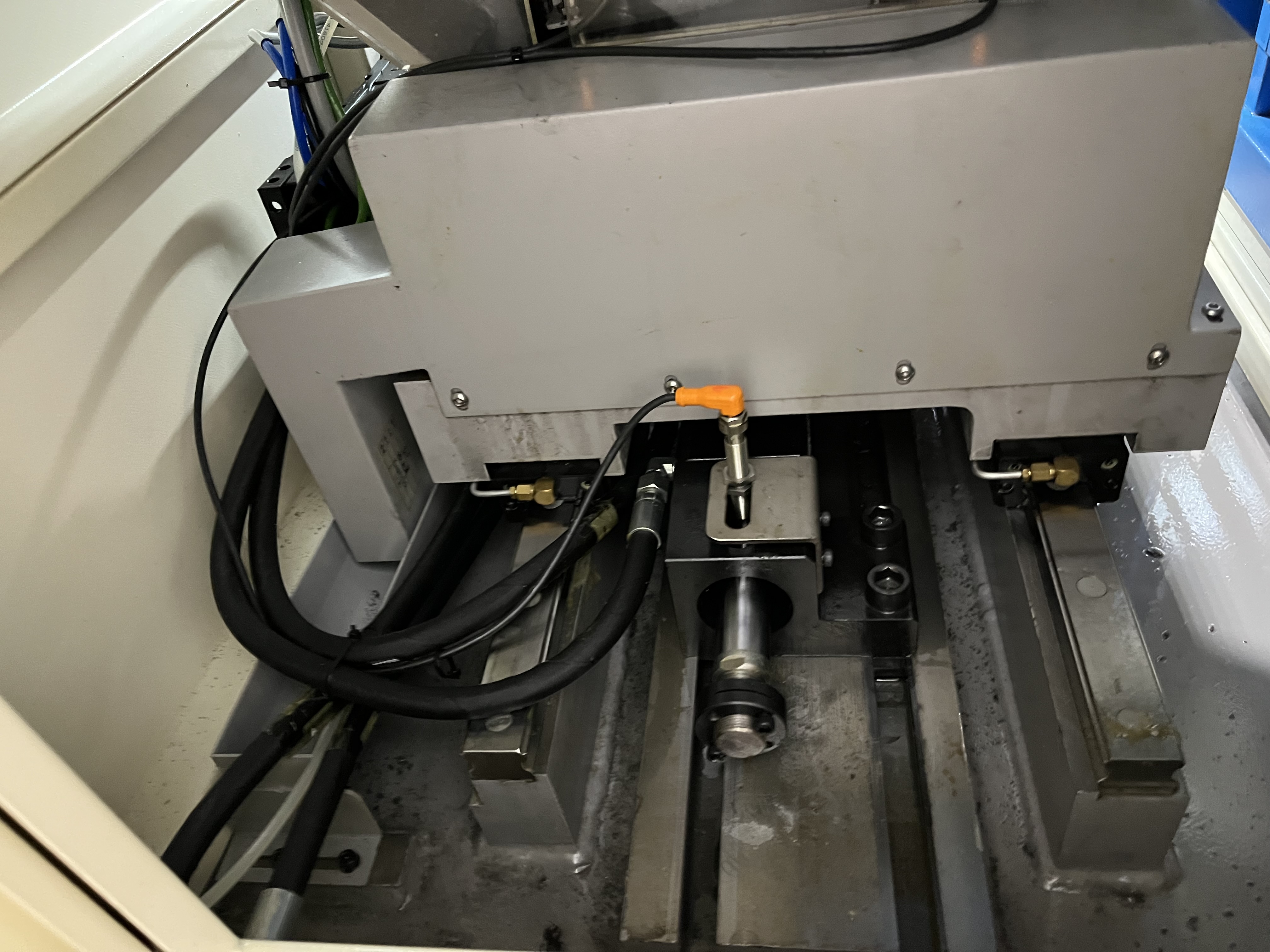
I dial in parameters in a specific order. Skip ahead and you’ll chase problems that were avoidable. Here is my workflow for setting up a new deep hole drilling job.
This guide assumes you already understand the basics. For a deeper look at the underlying theory, see my parameter guide. For material-specific speed and feed tables, check the speeds and feeds reference.
My Step-by-Step Workflow
I start from the work material and work forward. Each step depends on the one before it.
1. Identify Work Material
Before I touch the machine, I confirm material type, hardness, and condition. AISI 4140 at 30 HRC needs different parameters than the same alloy at 45 HRC. Cast iron behaves nothing like 316 stainless.
I check the material certificate or test a hardness spot. If the material is gummy (low-carbon steel, aluminum), I plan for higher coolant pressure and sharper geometry. If it’s hard (above 40 HRC), I plan for lower speeds and higher pressure.
2. Choose Drill Diameter and Geometry
Diameter drives the RPM calculation, and it also dictates the starting feed range. Larger drills above 25 mm can handle heavier feeds. Small drills under 6 mm need very light feeds and higher coolant pressure — I typically start at 1500 psi or more.
Gun drill geometry also matters. Standard geometry works for most carbon steels. High-helix or notched geometries help with stringy materials. I pick the geometry before I calculate speeds.
3. Select Cutting Speed
Cutting speed is surface speed, not RPM. I start from the tool manufacturer’s recommendations for the material. My typical starting points:
- Low-carbon steel: 80–120 SFM (24–37 m/min)
- Alloy steel (30–40 HRC): 60–90 SFM (18–27 m/min)
- Stainless steel (304/316): 40–60 SFM (12–18 m/min)
- Cast iron: 100–140 SFM (30–43 m/min)
- Aluminum: 200–350 SFM (61–107 m/min)
- Titanium alloys: 30–50 SFM (9–15 m/min)
I pick the middle of the range for a starting point, then adjust down if tool life is poor or up if chip shape is favorable.
4. Calculate RPM
RPM follows from cutting speed and diameter:
RPM = (Cutting Speed × 3.82) / Diameter (inches)
Or in metric: RPM = (Cutting Speed × 1000) / (π × Diameter in mm)
Example: 0.5-inch drill in alloy steel at 80 SFM → RPM = (80 × 3.82) / 0.5 = 611 RPM.
I round to the nearest available RPM on the machine. Going slightly slower is safer than faster.
5. Set Feed Rate
Feed rate is the most impactful parameter for productivity, but it also affects chip formation most directly. I start at the middle of the manufacturer’s range, typically:
- Gun drilling steel: 0.0005–0.002 in/rev (0.013–0.051 mm/rev)
- BTA / ejector drilling larger diameters: 0.002–0.006 in/rev (0.051–0.152 mm/rev)
- Aluminum (gun drill): 0.002–0.004 in/rev (0.051–0.102 mm/rev)
The feed affects chip thickness. Too light, and chips come out as fine dust or long ribbons. Too heavy, and the tool edge can break down. I look for the feed that produces short, half-moon chips roughly 1–3 mm wide.
6. Set Coolant Pressure and Flow
Coolant does three things: lubricate the cutting zone, cool the tool, and flush chips out of the bore. I set pressure first, then check flow.
Starting pressures:
- Gun drilling under 10 mm: 1500–2000 psi (100–140 bar)
- Gun drilling 10–25 mm: 1000–1500 psi (70–100 bar)
- Gun drilling over 25 mm: 800–1200 psi (55–85 bar)
- BTA drilling: 300–600 psi (20–40 bar)
I check coolant return at the bushing. Steady, continuous flow means pressure is adequate. If flow sputters or stops, chips are packing.
7. Set Peck Cycle
Pure gun drilling often runs continuous with no peck, because coolant through the tool clears chips continuously. But for smaller drills or deep holes (over 50× diameter), I add a peck:
- Peck depth: 5–10× drill diameter
- Retract distance: enough to clear chips — I use at least 3× diameter
- Dwell at retract: 0.5–1 second to let coolant flush the hole
For BTA drilling, pecking is rarely needed because chips exit through the inner tube continuously.
8. Drill a Test Hole
I run the first test hole on a short depth — maybe 2–3× diameter — to check chip shape, surface finish, and spindle load. Then I go full depth.
This is where I actually learn if the parameters are right.
How to Read Chip Shape
Chips tell me more about my parameters than any sensor. Here is what I look for:
| Chip Shape | Appearance | What It Indicates |
|---|---|---|
| Short half-moon, 1–3 mm wide | Curled, even width, breaks cleanly | Optimal parameters — feed and speed are balanced |
| Long ribbons or stringers | Continuous, unbroken, tangles | Feed too low or material is stringy; increase feed or use a chip breaker geometry |
| Needle / chip dust | Very fine shards, almost powder-like | Speed too high, feed too low, or tool wear; reduce speed or increase feed |
| Crowded / packed chips | Chips jammed together, stuck at bushing outlet | Coolant pressure too low, or retract insufficient; increase pressure or peck frequency |
| Discolored (blue / burnt) | Heat tint on chips, often blued steel | Speed too high or coolant inadequate; reduce speed or increase coolant flow |
If I see anything other than short half-moon chips, I stop and adjust before running production.
Adjusting When Tool Life Is Too Short
Short tool life usually means one of three things: speed is too high, coolant is inadequate, or the feed is too light (causing rubbing).
First thing I check: chip color. If chips are blue or dark brown, speed is too high. I reduce cutting speed by 10–15% and retest. For example, if I started at 80 SFM on 4140, I drop to 68–72 SFM.
Second: coolant concentration and pressure. Below 5% concentration, lubricity drops and edge wear accelerates. I target 8–12% for gun drilling steel. I also verify pressure at the tool tip, not at the pump — pressure drops across seals and bushings.
Third: feed rate. Counterintuitive, but raising feed can extend tool life. A feed that is too light creates foil-thin chips that don’t carry heat away. I increase feed by 10–20% and check chip shape. Heavier chips absorb more heat and leave the tool cooler.
Adjusting When Surface Finish Is Poor
Poor surface finish in deep hole drilling is almost always a vibration or burnishing problem.
I check the bushing first. A worn or misaligned bushing causes the drill to wobble, and no parameter change will fix that. Bushing clearance should be 0.0005–0.002 in (0.013–0.050 mm) over the drill diameter.
If the bushing is good, I look at the guide pad condition. Worn guide pads leave chatter marks on the bore wall. I replace them if they show edge rounding or galling.
If hardware is fine, I adjust parameters:
- Reduce feed: drop feed by 10–15% to reduce cutting forces and deflection
- Adjust RPM: lower RPM reduces forced vibration; raise RPM may push past the resonant band
- Increase coolant pressure: more pressure lifts chips away from the bore wall and stops them from scoring the finish
I rarely chase surface finish beyond three adjustments. If it is not improved, the issue is likely tool geometry or bushing alignment, not parameters.
Adjusting When Chips Are Packing
Chip packing is dangerous. Packed chips can wedge against the bore wall and seize the tool.
I check three things in order:
Coolant flow at the bushing — If flow is weak or inconsistent, pressure or delivery is the problem. I raise pressure by 200–300 psi and check again.
Retract cycle — When peck drilling, the retract distance must be long enough to dump chips. I set retract to at least 3× drill diameter. If chips still pack, I increase peck frequency (shorter peck depth).
Feed vs. chip breaker — Some materials need a chip breaker notch on the drill tip. If I am running a standard grind in a gummy material (1018 low carbon, 304 stainless), I switch to a notched tip before adjusting speed or feed.
If chips pack at the drill entry (around the bushing), the issue is usually insufficient flow at the start. I add a dwell or a reduced feed at the entry point for the first 0.1 inches of depth.
Parameter Adjustment Troubleshooting
Here is a quick-reference table I keep at the machine:
| Symptom | Likely Cause | What to Change |
|---|---|---|
| Blue chips, rapid edge wear | Speed too high | Reduce cutting speed 10–15% |
| Long ribbon chips, tangling | Feed too low | Increase feed 15–25% |
| Chip dust / needle chips | Speed too high or feed too low | Reduce speed 10% or increase feed 15% |
| Poor surface finish, chatter | Bushing wear, guide pad wear, or vibration | Inspect bushing and pads; reduce feed 10–15% or adjust RPM band |
| Chips packing at bushing | Insufficient coolant pressure or flow | Increase pressure 200–300 psi; check for blockages |
| Tool breakage near entry | Feed too high on entry or insufficient entry dwell | Reduce entry feed or add 0.010 in dwell at entry |
| Oversize hole | Bushing loose, guide pad worn, or feed too high | Check bushing fit; replace pads; reduce feed |
| Undersize hole | Burnishing from low speed or dull tool | Raise speed 10% or replace tool |
Key Takeaways
Cutting speed comes first, feed and pressure follow. RPM is a calculation, not a guess.
Chips are the best feedback loop. Short half-moon chips mean the parameters are in the right window. Anything else means something is off — change one variable at a time and observe.
Tool life, surface finish, and chip packing each point to different root causes. Speed affects heat and wear. Feed affects chip shape and thickness. Coolant pressure affects chip evacuation and bore quality.
Change one parameter at a time. If I adjust speed and feed and pressure in the same test, I won’t know which one fixed the problem.
Every material, diameter, and machine combination is different. Use the starting points here, but let your chips tell you the final answer.