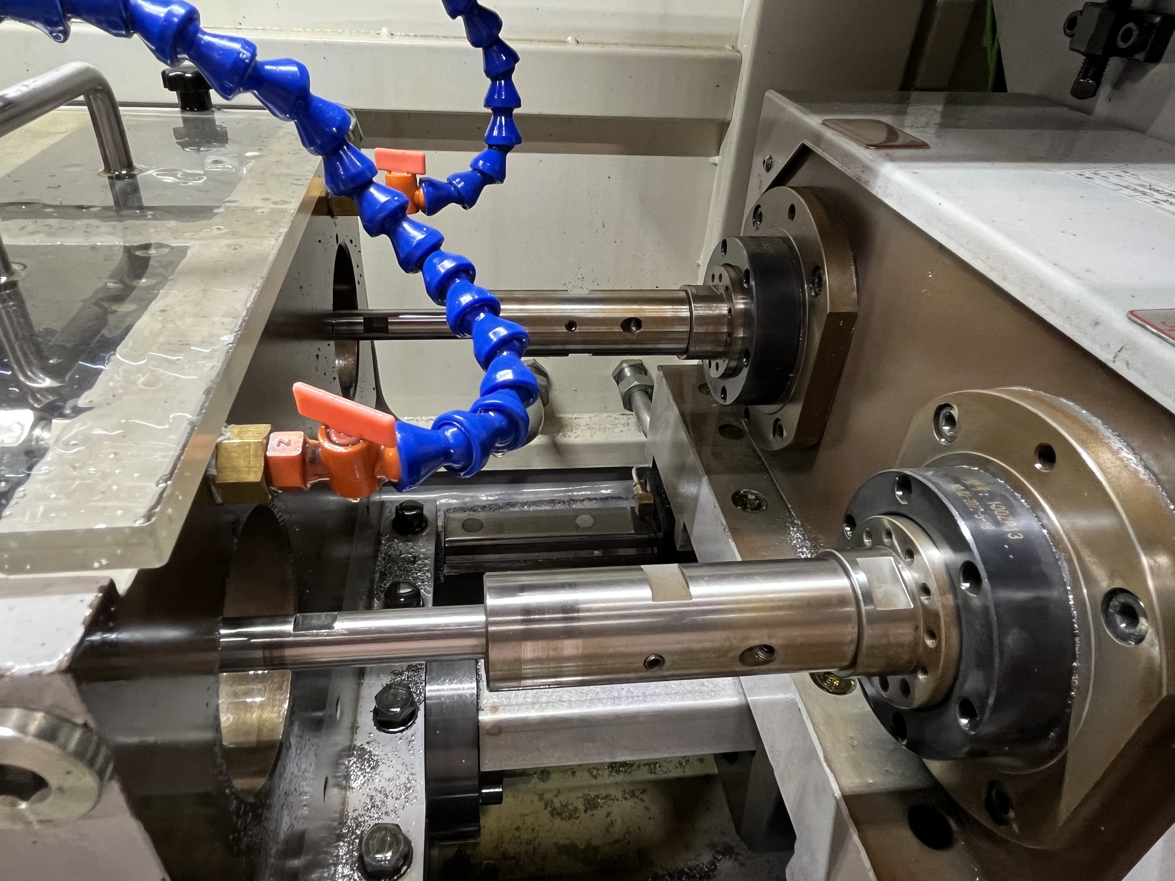
I plan each job in seven steps before touching the machine. Good planning prevents problems during production. I have learned through experience that skipping any of these steps leads to scrapped parts and broken tools.
I developed this checklist after enough failures to know better. Here is my complete planning process for a deep hole drilling job.
Step 1: Review the Print
I start with the print review. I check hole diameter, depth, tolerance, surface finish, and material grade. These five factors determine everything else in the plan.
The depth-to-diameter ratio is the first number I calculate. A ratio under 10:1 is straightforward. At 20:1, I need peck cycles and careful parameters. At 50:1, I need specialized tooling and a pilot hole.
I also check for cross holes or features that might cause interrupted cuts. A cross hole at the drilling depth will deflect the drill and may break it. I plan to drill first and machine cross holes after when possible.
Here is how I categorize jobs based on print review:
| Depth Ratio | Difficulty | Typical Applications |
|---|---|---|
| Under 10:1 | Easy | Standard bolt holes, oil passages |
| 10:1 to 30:1 | Moderate | Hydraulic cylinders, spindles |
| 30:1 to 50:1 | Difficult | Gun barrels, long shafts |
| Over 50:1 | Extreme | Medical implants, aerospace |
Step 2: Select the Process
I choose between gun drilling, BTA drilling, or ejector drilling based on the diameter and production quantity.
- Gun drilling: 1-50mm diameter, any quantity, best for small diameters and precision
- BTA drilling: 20-200mm diameter, high production, best for large diameters
- Ejector drilling: 20-100mm diameter, where through-coolant BTA is not feasible
Gun drilling is my default choice for diameters under 50mm. BTA is better for diameters over 30mm in production runs. There is some overlap where either process works.
For the decision, I consider the material removal rate and the required hole straightness. Gun drilling gives better straightness for small diameters.
Step 3: Select Tooling
I choose the drill diameter, coating, and guide bushing based on the material. The drill diameter is the finish diameter for gun drilling. No reaming is needed.
For the coating, I use:
- TiAlN: General purpose for steels
- AlTiN: High-temperature alloys like Inconel
- Uncoated: Aluminum, brass, plastics
- Diamond: Composites and abrasive materials
The guide bushing selection depends on the workpiece material and the start surface. I use a hardened steel bushing for steel parts and a carbide bushing for abrasive materials.
Step 4: Set the Parameters
I calculate RPM, feed rate, and coolant pressure using material-specific recommendations.
For a 10mm hole in 4140 steel:
- Cutting speed: 60 m/min
- RPM: 60 x 1000 / (Pi x 10) = 1910 RPM
- Feed rate: 0.04 mm/rev
- Feed speed: 1910 x 0.04 = 76 mm/min
- Coolant pressure: 1500 psi
I start at the middle of the recommended range and adjust based on chip formation. Short, broken chips are the target.
Step 5: Plan the Setup
I determine the workholding, steady rest positions, and alignment checks needed. The setup must resist the torque and thrust of drilling while maintaining alignment.
For long workpieces, I plan steady rest positions every 10x the workpiece diameter. The steady rests prevent vibration and hole wander.
The alignment check list:
- Spindle to guide bushing: within 0.01mm
- Guide bushing to workpiece: within 0.02mm
- Workpiece centerline to spindle axis: within 0.01mm
Step 6: Run the First Part
I drill the first part and inspect it thoroughly before continuing. The first part inspection includes:
- Hole diameter at both ends and mid-depth
- Surface finish at multiple depths
- Hole straightness using a pin gauge or CMM
- Chip examination for color and shape
I do not change any parameters during the first hole. I run it at the planned settings and evaluate the results. Changing parameters mid-hole confuses the data.
Step 7: Adjust and Run Production
I fine-tune parameters based on the first part results and then run the batch. Typical adjustments are 5-10% changes to speed or feed.
If the surface finish is rough, I reduce the feed rate or increase the speed. If the tool shows edge wear, I reduce the speed. If the chips are too long, I increase the feed or reduce the peck length.
I inspect every fifth part during production and check the tool at every tool change.
Key Takeaways
- Always follow the seven-step plan before starting a new job
- The depth-to-diameter ratio determines the difficulty level
- Choose the process (gun drill, BTA, ejector) based on diameter and production volume
- Start parameters at the middle of the recommended range and adjust by 5-10%
- Inspect the first part thoroughly before running production
- Check every fifth part during the production run
For more on specific materials, see my guide on deep hole drilling in difficult materials.