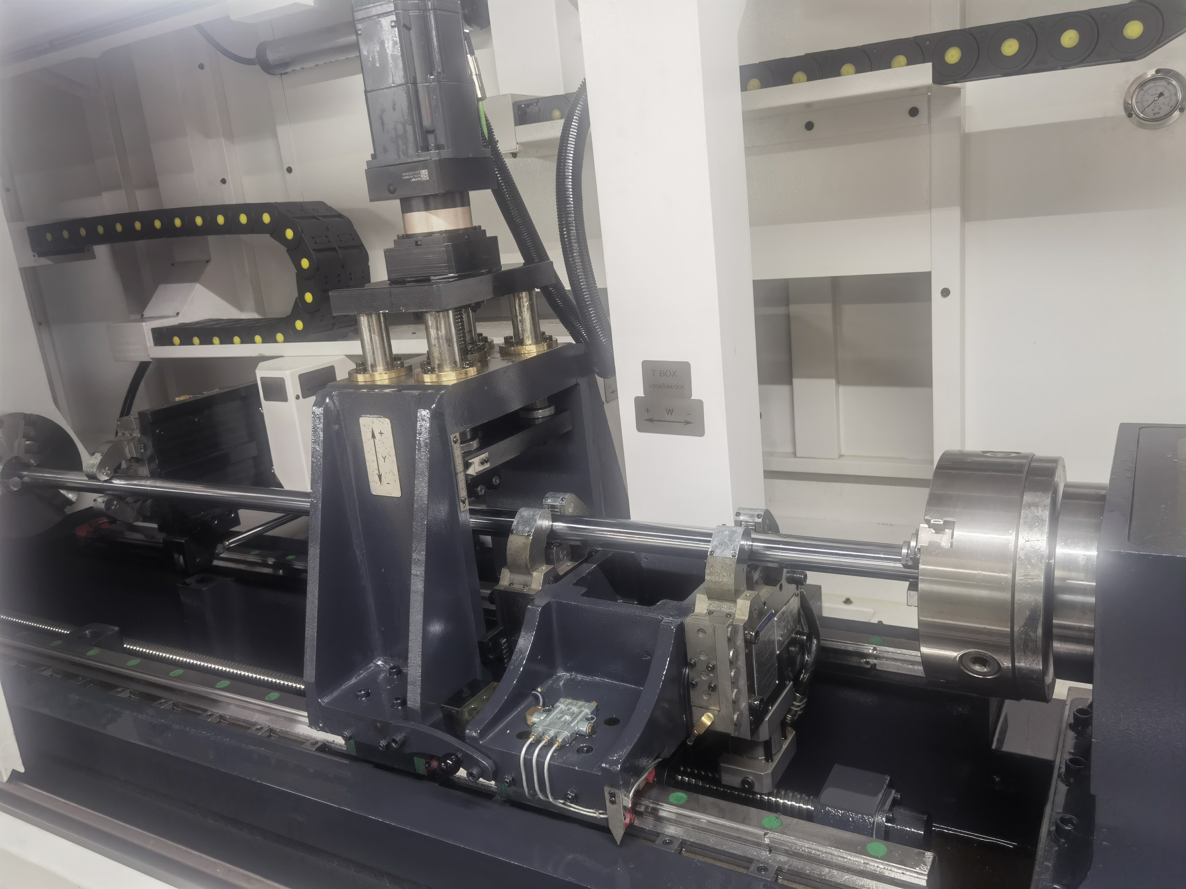
I have spent years dialing in gun drilling parameters for steel, aluminum, and titanium. When the first batch of PEEK medical components landed on my desk, I assumed the same principles would apply with lighter cuts. I was wrong. Plastics and composites behave fundamentally differently under the cutting edge, and deep hole drilling amplifies every one of those differences. Here is what I have learned the hard way so you do not have to.
Material Differences: Amorphous vs Semi-Crystalline vs Filled
The first thing to understand is that not all plastics cut the same way. Amorphous plastics like polycarbonate, ABS, and acrylic have a random molecular structure with no defined melting point — they soften gradually. This means they tend to gum up the drill flute as heat builds, especially in deep holes where chip evacuation is already the bottleneck.
Semi-crystalline plastics like PEEK, Delrin (acetal), and nylon have an ordered molecular structure and a sharp melting point. Below that temperature they are stiff and machine cleanly. Exceed it — even locally at the cutting edge — and they turn into a sticky mess instantly. I have ruined more Delrin parts by pushing feed too hard than by any other mistake. The chip transitions from a clean shear to a molten smear in the span of a single revolution.
Filled and reinforced materials add another layer of complexity. Glass-filled PEEK, carbon-fiber-reinforced nylon, and mineral-filled acetal are abrasive. The filler acts as a grinding medium that wears tool edges rapidly. I have measured edge radius doubling after as few as 50 holes in 30% glass-filled PEEK. This is where carbide tooling moves from nice-to-have to mandatory.
Chip Formation in Plastics: Melting vs Cutting
In metal gun drilling, the chip forms through shear deformation and breaks naturally against the drill margin. In plastics, the chip wants to stay continuous and elastic. If the edge is not razor-sharp, the material deforms plastically instead of shearing, generating frictional heat that pushes the plastic past its glass transition temperature.
The result is a melted ribbon that wraps around the drill shank, plugs the gullet, and seizes the tool in the hole. I have extracted more broken drills from plastic parts than from steel parts combined, and every single failure traced back to inadequate chip breaking.
The remedy is a tool geometry that forces the chip to curl and fracture. Higher feed per revolution helps by increasing chip thickness to a point where the chip cannot bend without fracturing. I run feeds roughly 30-50% higher in unfilled plastics than I would in mild steel of equivalent hole depth, always keeping one eye on the torque readout.
Tool Geometry for Plastics
Standard gun drill geometries designed for metals will not work well on plastics. The cutting edge needs to be sharper — typically a 6-8 degree primary relief versus the 10-12 degrees common for steel. This provides a clean shearing action rather than a scraping burnishing action that generates heat.
Rake angle is critical. For amorphous plastics I use a slightly positive rake of 3-5 degrees. For semi-crystalline materials like PEEK and Delrin, a neutral to 2-degree positive rake gives the best balance of cutting action and edge strength. For filled materials, I back off to a 0-2 degree positive rake with a small edge hone to prevent microchipping from abrasive filler particles.
The nose radius must also be smaller — 0.02 to 0.05 mm versus the 0.10 mm I typically use for steel. A larger nose radius increases thrust force and heat generation, both of which are the enemy when drilling plastics.
For a deeper breakdown of gun drill geometry fundamentals, see my Gun Drill Geometry Guide.
Coolant Considerations
Coolant chemistry compatibility with plastics is a topic that gets almost no attention until you have a batch of cracked parts. Some plastics are susceptible to environmental stress cracking when exposed to certain coolants. Polycarbonate, for instance, will craze and crack on contact with alkaline coolants. Nylon absorbs water and swells, changing dimensions unpredictably.
My coolant strategy depends on the material:
- Unfilled PEEK and Delrin: Straight oil or high-lubricity water-soluble coolant at 5-8% concentration. These materials are chemically stable and the priority is lubricity to reduce frictional heating.
- Nylon: Oil-based coolant to minimize water absorption. If I must use water-soluble coolant, I keep concentration above 10% and dry the parts immediately after drilling.
- Polycarbonate and acrylic: Avoid coolant altogether if possible — compressed air or mist lubrication only. If coolant is required for hole quality, use a neutral-pH synthetic coolant with no amines.
- Filled materials: High-flow coolant is non-negotiable. The abrasive debris requires aggressive flushing to prevent recutting and tool wear. I use 70-100 psi coolant pressure even in shallow deep holes.
Parameter Recommendations
The table below summarizes the starting parameters I use for common plastic and composite materials in gun drilling applications. Always adjust based on hole diameter and depth-to-diameter ratio.
| Material | Speed (SFM) | Feed (IPR) | Coolant | Expected Finish |
|---|---|---|---|---|
| Unfilled PEEK | 200-350 | 0.002-0.005 | Oil / high-lubricity soluble | Excellent — burnished bore |
| Delrin (Acetal) | 300-500 | 0.003-0.006 | Oil / soluble 5-8% | Excellent — mirror finish possible |
| Nylon 6/6 | 250-400 | 0.002-0.005 | Oil-based preferred | Good — slight porosity possible |
| Polycarbonate | 150-250 | 0.001-0.003 | Mist / compressed air | Good — watch for stress cracking |
| 30% Glass-filled PEEK | 150-250 | 0.002-0.004 | High-flow soluble | Fair — abrasive wear visible |
| Carbon-fiber nylon | 200-350 | 0.002-0.004 | High-flow soluble | Fair — fiber pullout possible |
| Acrylic | 100-200 | 0.001-0.002 | Compressed air | Good — requires sharpest edge |
Start at the lower end of the speed range and work up. Plastic is more forgiving of high feed than high speed — speed generates heat through friction while feed generates heat through shear, and plastic handles shear heat much better.
Common Problems
Over the years I have developed a mental checklist for troubleshooting plastic deep hole drilling. Every problem I have encountered falls into one of these categories.
| Problem | Cause | Fix |
|---|---|---|
| Molten chip packing in flute | Excessive speed or dull edge | Reduce RPM, increase feed, inspect edge radius |
| Smearing on bore surface | Insufficient relief angle or coolant | Increase primary relief, verify coolant flow at drill tip |
| Tool edge chipping | Abrasive filler or chatter | Add edge hone, reduce feed variation, check bushing fit |
| Delamination (composites) | Excessive thrust force or dull drill | Reduce feed, verify edge sharpness, peck if needed |
| Part cracking near hole exit | Too much coolant pressure or thermal shock | Reduce coolant pressure, increase lubricity, or switch to air |
| Hole size drifting oversized | Tool wear or thermal expansion of plastic | Check edge condition, account for material thermal expansion in tool spec |
| Stringy bird-nest chips | Insufficient feed per revolution | Increase feed until chip fractures; if this hurts finish, reduce speed instead |
Delamination deserves special attention in composites. The interface between the plastic matrix and the reinforcement is the weak point. If the drill pushes through rather than cuts cleanly, the thrust force delaminates the layers at the hole exit. I always use a backup support on the exit side and keep the drill sharp — a dull drill doubles thrust force before you notice it in surface finish.
For a more detailed discussion on composite-specific challenges, see my Composite Material Drilling application note.
Key Takeaways
- Plastics are not soft metals. They require fundamentally different tool geometry — sharper edges, smaller nose radii, and careful attention to rake angle based on the polymer type.
- Heat is the enemy. Once a semi-crystalline plastic crosses its melting point at the cutting edge, chip evacuation fails catastrophically. Manage heat through speed reduction and coolant strategy, not just feed adjustments.
- Feed is your friend. Higher feed per revolution forces chip fracture and reduces time for heat to conduct into the workpiece. Speed generates heat; feed removes material.
- Coolant chemistry matters. Check chemical compatibility with every new plastic. Environmental stress cracking, water absorption, and chemical attack can scrap parts that look perfect on the surface.
- Filled materials wear tools fast. Plan for higher tool consumption and inspect edges frequently. Carbide with appropriate edge preparation is mandatory for any glass- or mineral-filled plastic.
- Support the exit. Delamination in composites and cracking in brittle plastics are exit-side problems. Backup support and a sharp drill are cheap insurance.