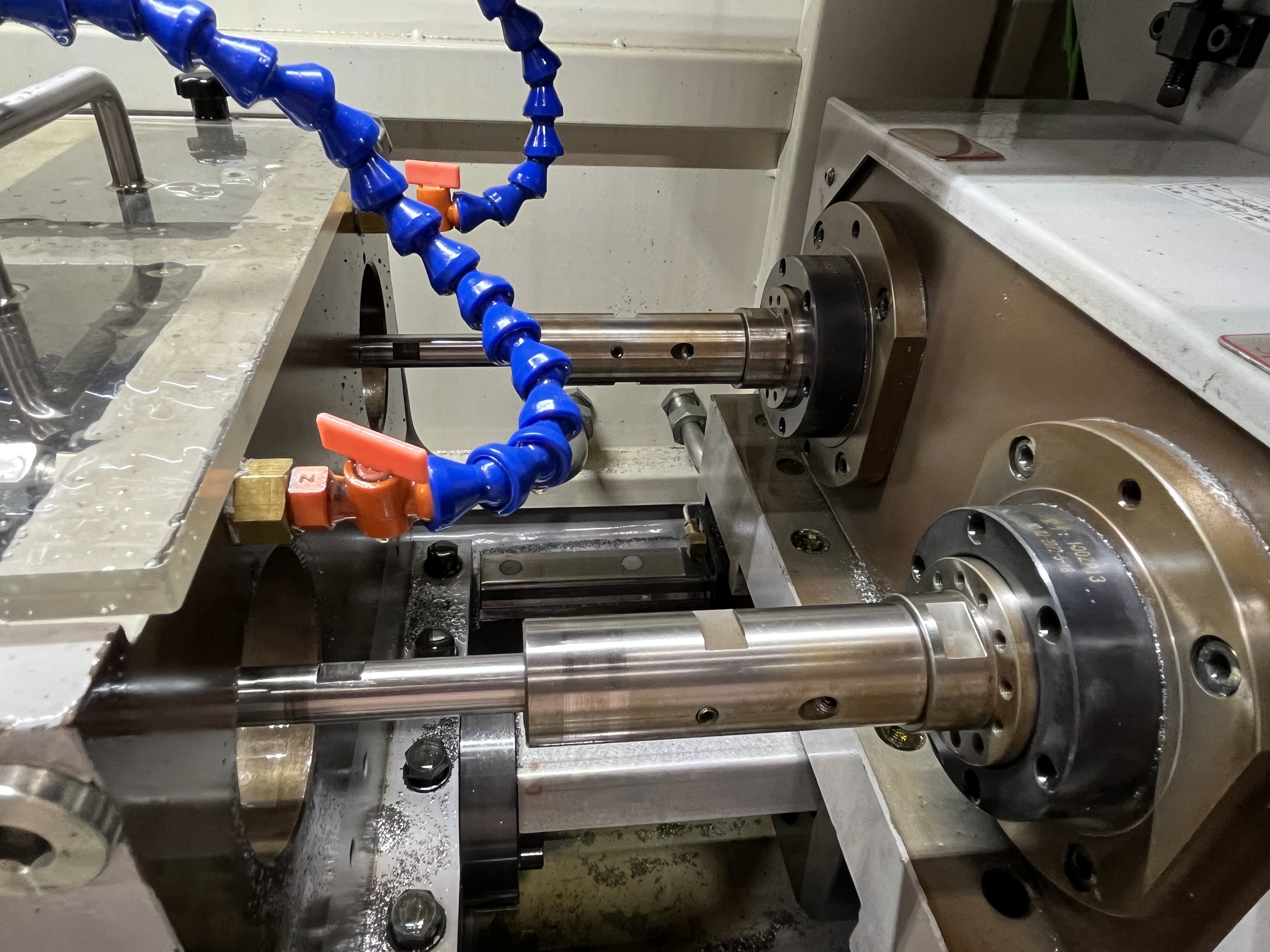
I use step drilling when the bore needs multiple diameters along its length. Step drilling creates a bore with different diameters at different depths, like a counterbore for a bolt head or a stepped shaft bore for hydraulic applications. It can also help manage chip evacuation and tool deflection in deep holes.
When to Use Step Drilling vs Single Diameter
Step drilling is not always the right choice. I use it in specific situations where a single-diameter hole will not work. Here is how I decide.
| Application | Step Drilling | Single Diameter | Reason |
|---|---|---|---|
| Hydraulic cylinder port with O-ring groove | Preferred | Not suitable | Need two diameters for seal groove |
| Bolt counterbore for flush mounting | Preferred | Not suitable | Need stepped recess |
| Deep hole with chip clearance issues | Consider | Preferred for standard | Step provides chip relief at entry |
| Precision bearing housing | Preferred | Not suitable | Different diameters for bearing and shaft |
| Coolant passage in shaft | Not needed | Best choice | Single diameter sufficient |
| Through-hole for wiring harness | Not needed | Best choice | No functional need for step |
The decision also comes down to tooling cost. A step drilling operation with two separate tools costs less in tooling than a combined step drill. For runs under 500 parts, I use two tools. For runs above 500 parts, a combined step drill pays for itself through reduced cycle time.
The Step Drilling Sequence
The standard sequence I follow is to drill the smallest diameter first to the full depth of the part. That smaller hole acts as a pilot for the larger drill that follows. Enlarging the entry section with a larger tool ensures concentricity between the two diameters.
For a typical hydraulic cylinder port, I drill a 20 mm through-hole first, then open the top 50 mm to 30 mm for the O-ring groove. The pilot hole guides the larger drill and prevents it from wandering off-center.
I keep the difference between successive diameters to 10 mm or less. Stepping from 20 mm to 40 mm in one pass puts too much cutting force on the larger drill and can cause chatter. Spreading the step over two operations gives better control. If the step difference must exceed 10 mm, I use an intermediate diameter between the two.
Industry Applications for Step Drilling
Step drilling is used across many industries where complex hole geometries are required. Here are the applications I have encountered:
| Industry | Specific Application | Step Configuration | Tooling Approach |
|---|---|---|---|
| Aerospace | Hydraulic actuators, landing gear components | Counterbore for seal grooves | Two-tool sequence |
| Automotive | Crankshaft oil passages, engine blocks | Stepped oil galleries | Combined step drill |
| Hydraulics | Valve blocks, cylinder ports | O-ring groove + through-hole | Two-tool or stepped bushing |
| Oil and gas | Downhole tools, drill string components | Multi-diameter bores for threaded connections | Two-tool sequence with BTA |
| Mold and die | Cooling channels in plastic injection molds | Stepped passages for baffles | Two-tool sequence |
| Medical | Bone screws, surgical instruments | Simple counterbore | Combined step drill |
Tool Selection for Step Drilling
Not every tool works well for step drilling. Here is what I use:
| Tool Type | Best For | Limitations |
|---|---|---|
| Standard carbide gun drill | Long, deep steps | Requires pilot hole |
| Step drill (combined diameter tool) | Short steps, high production | Expensive, long lead time |
| Indexable BTA head | Large diameters, roughing | Not for finish |
| Carbide boring bar | Precision steps | Slower, material specific |
A combined step drill has both diameters ground into the same tool. It drills both diameters in one pass but costs three to four times more than a standard drill. I only use combined step drills for production runs above 500 parts where the cycle time savings justify the tool cost. The combined step drill also requires a more expensive regrind because both diameters need to be sharpened.
For two-tool step drilling, I choose the pilot drill diameter at about 60 percent of the final diameter. Research on step drill geometry has shown that the small diameter should not be less than 60 percent of the large diameter for optimal cutting performance. Below that ratio, the larger tool experiences uneven loading and the transition zone becomes difficult to control.
Transition Geometry and Stress Relief
The step between diameters needs careful thought. The transition should have a radius or chamfer to reduce stress concentration. A sharp 90-degree step creates a stress riser that can cause part failure under cyclic loading.
| Transition Type | Stress Concentration Factor | Application |
|---|---|---|
| Sharp 90-degree corner | 2.5-3.0 | Non-critical, static loads |
| 0.5 mm radius | 1.5-1.8 | Moderate cyclic loads |
| 2.0 mm radius | 1.2-1.3 | High-cycle fatigue |
| 45-degree chamfer | 1.4-1.6 | General purpose |
| 30-degree chamfer | 1.3-1.5 | Hydraulic applications |
I always add a minimum 0.5 mm radius at the step for hydraulic components. Pressure testing has shown that sharp corners in hydraulic cylinders fail within 50,000 cycles at 200 bar. The same part with a 1 mm radius runs past 500,000 cycles without failure.
Feed Rate Management at the Transition
Feed rate at the step transition needs to be reduced by about 30 percent. When the larger drill reaches the step, the cutting forces change suddenly as the full cutting edge engages the material. The reduced feed prevents tool damage and chatter.
I program the feed reduction to start 2 mm before the step depth and resume 2 mm after. The gradual transition avoids a sudden load change that could chip the cutting edge. For a 30 mm step drill feeding at 0.08 mm/rev, I reduce to 0.05 mm/rev through the transition zone.
I also reduce the spindle speed by 10-15 percent at the step depth. The reduced speed lowers the impact force when the larger diameter engages the material. I have found that combining feed reduction with speed reduction gives better results than feed reduction alone.
Coolant Considerations for Step Drilling
Coolant delivery becomes more complex with step diameters. The pilot hole is smaller than the final bore, so a standard coolant bushing for the larger diameter does not seal properly during the initial small-diameter drilling.
I use one of two approaches:
- Drill the small hole using a bushing that matches its OD, then switch to the larger bushing for the step operation.
- Use a stepped bushing with two sealing diameters machined as one piece.
The two-bushing approach is simpler and cheaper. The stepped bushing is better for production runs where tool change time matters. I have also used custom bushings with replaceable inserts that allow bushing diameter changes without removing the entire bushing from the machine.
Coolant pressure needs to be maintained at the higher diameter’s requirement even during the small-diameter drilling phase. I set the pressure regulator for the final step diameter and let the smaller pilot hole run at the same pressure. The smaller drill can handle the higher pressure, and the chip evacuation is better than running at reduced pressure.
Common Problems and How I Avoid Them
Chatter during step drilling is the most common issue I see. It usually happens because the shoulder engagement causes interrupted cutting. Reducing the speed by 10-20 percent at the step depth eliminates most chatter.
Tool breakage at the step is the second most common problem. A larger diameter tool contacting the step shoulder on one side only creates uneven loading. I check concentricity between the pilot and the stepped bore by running a test bar after setup. If the runout between diameters exceeds 0.05 mm, I correct the alignment before drilling production parts.
Chip packing at the step transition is the third issue. When the larger drill engages, it produces larger chips that must exit through the smaller pilot section of the bore. If the step depth is more than 5x the pilot diameter, chips can pack at the transition. I address this by programming a chip-clearing retract at the step depth before continuing deeper.
Key Takeaways
- Step drilling is a practical technique for deep holes that need multiple diameters, and it is common in hydraulic and pneumatic components where ports and seal grooves are required.
- The small diameter should be at least 60% of the large diameter for optimal tool loading and transition quality.
- Use a two-tool sequence for runs under 500 parts; a combined step drill pays off for higher production volumes.
- Transition geometry matters: add a minimum 0.5 mm radius for hydraulic applications to prevent fatigue failure.
- Reduce feed by 30% and speed by 10-15% at the step transition to prevent chatter and tool breakage.
- Check concentricity between pilot and stepped bore — runout over 0.05 mm causes uneven tool loading.
- Use a stepped bushing or two-bushing approach to maintain coolant seal across both diameters.
- Program a chip-clearing retract at the step depth if the step is deeper than 5x the pilot diameter.
- For more on coolant system requirements, see my guide on coolant pump troubleshooting. For related deep hole techniques, see my guide on deep hole drilling in difficult materials.