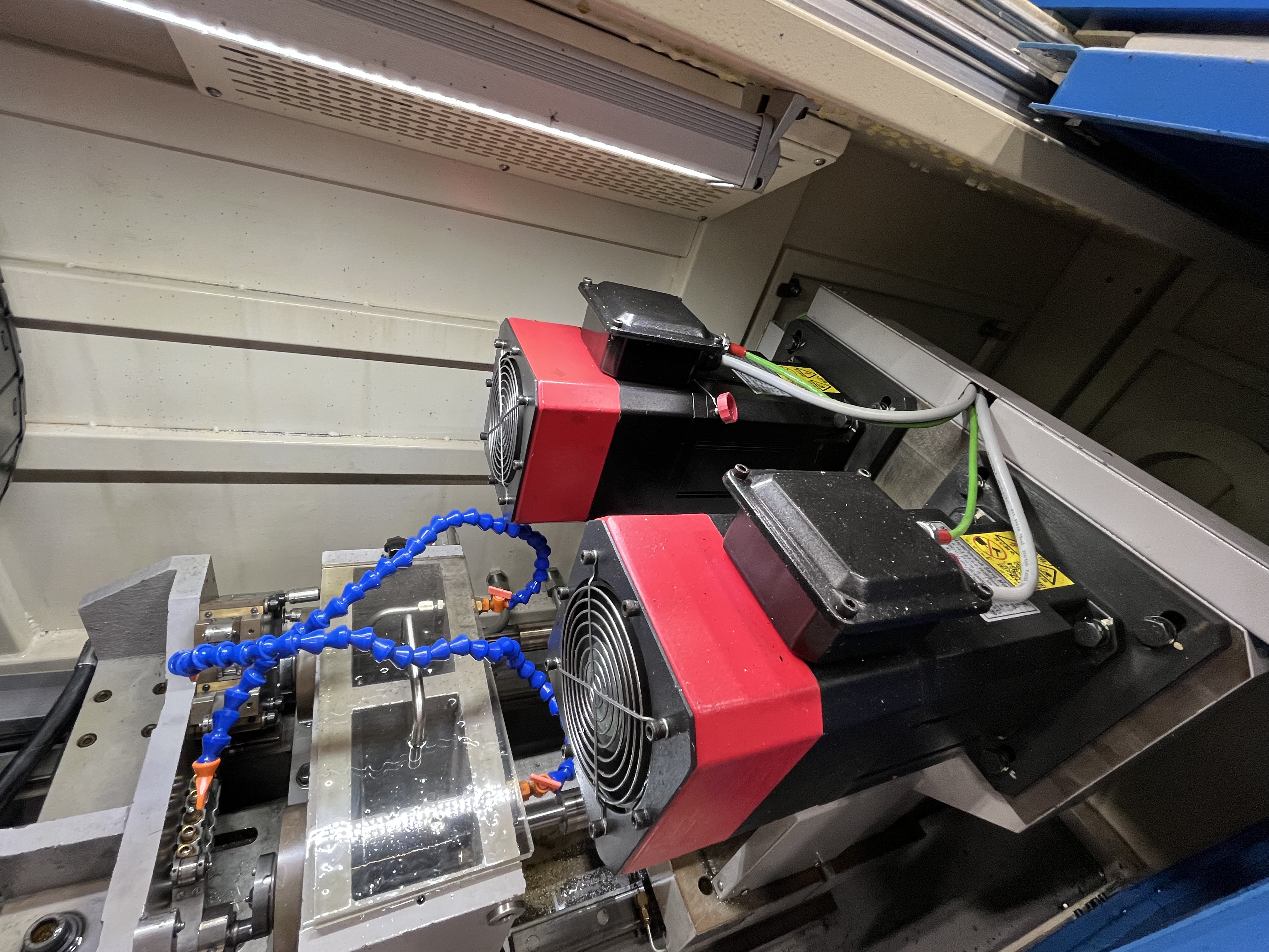
Tool load monitoring tracks the spindle load during drilling and alerts the operator when the load exceeds a threshold. It catches problems before the drill breaks. In my experience, load monitoring saves more tools than any other preventive measure I have implemented in my shop.
I set up the monitoring on the CNC control. The control reads the spindle drive current and compares it to the baseline measured during the first cycle with a fresh tool. I set the alarm threshold at 120% of baseline and the stop threshold at 150%. These numbers are starting points — I adjust them for each material and application.
Setting Up the Monitoring System
The monitoring requires a baseline measurement first. I run the first hole with a new tool and record the steady-state load. The baseline includes the load from the cutting forces and the coolant pressure through the tool. I take the baseline reading at the full-depth cutting portion of the cycle, not during entry or exit where the load is lower.
Most modern CNC controls have built-in load monitoring that reads the spindle drive current. The control converts the current reading to a percentage of the drive rating. I set the alarm to trigger at 120% and the stop at 150% of the recorded baseline. The control scans the load every 10-20 milliseconds during cutting, which gives enough resolution to catch sudden spikes.
Load Monitoring Methods Comparison
There are several ways to monitor tool load. The method I use depends on the machine capability and the criticality of the job.
| Method | Sensor | Response Time | Sensitivity | Cost | Best For |
|---|---|---|---|---|---|
| Spindle drive current | Built into drive | 10-20 ms | Moderate (measures motor load) | Free (built-in) | Most applications, easy setup |
| Spindle power monitor | Power transducer | 5-10 ms | Good (measures actual power) | Low-Moderate | Higher sensitivity than current alone |
| Torque sensor (strain gauge) | Tool holder strain gauge | 1-5 ms | Excellent (direct torque reading) | High | Critical jobs, expensive parts |
| Feed force sensor | Table or spindle load cell | 2-5 ms | Excellent (measures thrust) | High | Deep hole drilling, BTA applications |
| Acoustic emission | AE sensor on spindle | <1 ms | Very High (detects micro-cracks) | Very High | Research, development, ultra-critical |
| Vibration sensor | Accelerometer | 1-2 ms | High (detects chatter) | Moderate | Combined with load monitoring |
For most production jobs, spindle drive current monitoring is sufficient. I only use torque sensors or feed force sensors on jobs where the part value exceeds $1,000 and a tool breakage would be catastrophic.
Threshold Setting Guide
The right threshold depends on the material, the depth of the hole, and the stability of the process. I start with the baseline and adjust based on experience with each material.
| Material | Baseline Load (%) | Alarm Threshold (%) | Stop Threshold (%) | Notes |
|---|---|---|---|---|
| 1018 mild steel | 80-90 | 120 | 150 | Tolerant, wide margin |
| 4140 steel (28-32 HRC) | 85-95 | 115 | 140 | Tighten thresholds for hardened |
| 316 stainless steel | 85-95 | 115 | 135 | Work-hardens, respond fast to spikes |
| 6061 aluminum | 70-85 | 120 | 150 | Low load, wide margin |
| 7075 aluminum | 75-85 | 115 | 140 | Higher load than 6061 |
| Inconel 718 | 90-100 | 110 | 130 | Tightest thresholds, fast response |
| Ti-6Al-4V | 85-95 | 115 | 140 | Watch for chip packing spikes |
| Cast iron | 75-85 | 125 | 160 | Abrasive but predictable |
I also set the window of monitoring. The load monitoring should only be active during the cutting portion of the cycle. Entry, exit, and peck retracts produce different load signatures that would trigger false alarms. I program the monitoring to activate 5mm into the cut and deactivate 5mm before the exit.
Load Pattern Recognition
The pattern of the load change tells me what is happening inside the hole. I train my operators to recognize four main patterns.
| Load Pattern | Time Scale | Typical Increase | Root Cause | Required Action |
|---|---|---|---|---|
| Gradual increase over many holes | 50-200 holes | 20-40% | Tool wear, edge dulling | Schedule tool change |
| Gradual increase within one hole | 5-30 seconds | 30-50% | Chip packing at drill tip | Retract, flush, check coolant pressure |
| Sudden spike, short duration | 0.5-2 seconds | 80-100% then drops | Hard spot in material | Continue if load drops; retract if repeat |
| Sudden spike, sustained | 1-3 seconds | 50-80% sustained | Coolant interruption | Stop immediately, retract, check coolant |
| Steady increase with depth | Per hole | 10-30% | Weld buildup on margin | Switch to coated drill, adjust coolant |
| Cyclical fluctuation | 2-5 second cycle | 20-40% | Chatter, vibration | Adjust RPM, check bushing fit |
| Erratic, unpredictable | Varies | 30-100% | BUE formation and breakoff | Increase speed, check coolant lubricity |
I have found that pattern recognition is the most valuable skill for load monitoring. A sudden spike that drops back to baseline is usually a hard spot — the tool is fine. A gradual increase that does not drop back is chip packing — the tool is at risk and needs action.
Alarm Response Procedure
When the monitoring system triggers an alarm, I follow a standardized response procedure. This prevents operators from making the wrong decision under pressure.
Alarm at 120-150% (Watch alarm): Complete the current hole, then inspect the tool edge under magnification. If the edge is intact, continue with the next hole. If the edge shows damage or wear, change the tool.
Alarm at 150%+ (Stop alarm): Retract the tool immediately. Inspect the drill for damage. Check the bore for chip packing with a borescope. Clear any packed chips. If the tool edge is damaged, replace the tool. If the tool is undamaged, resume at reduced speed and monitor the load closely.
I post this procedure on the machine control panel so every operator follows the same steps. For more on protecting your tools, see my guide on setting torque limits and the tool wear monitoring systems overview.
Real-World Results
I have caught several potential breakages with load monitoring. On one long production run in 316 stainless steel, the load increased gradually from 85% to 115% over 200 holes. The cutting edge looked fine under a microscope, but the load told the real story. I changed the tool preventively and found microchipping on the cutting edge that was invisible to the naked eye. The load monitoring saved a tool breakage that would have scrapped the part.
On another job in titanium Ti-6Al-4V, a sudden load spike stopped the spindle at 160% load. The drill was packed with chips at 180mm depth. A quick retract and flush cleared the chips, and the tool finished the hole without damage. Without load monitoring, the drill would have broken within another 10mm of feed.
Key Takeaways
- The monitoring system is already built into most CNC controls — it just needs to be enabled and configured properly
- Set alarm at 120% and stop at 150% of baseline as a starting point, then adjust per material
- A gradual load increase across holes means tool wear; a sudden spike means chip packing or hard spots
- Learn the four main load patterns — each tells a different story about what is happening at the cutting edge
- Adjust thresholds down for difficult materials like Inconel (stop at 130%) and up for forgiving materials like mild steel
- Monitor load trends across multiple holes, not just within one cycle — the trend tells the long-term story
- Follow a standardized response procedure when alarms trigger — don’t let operators decide on the fly