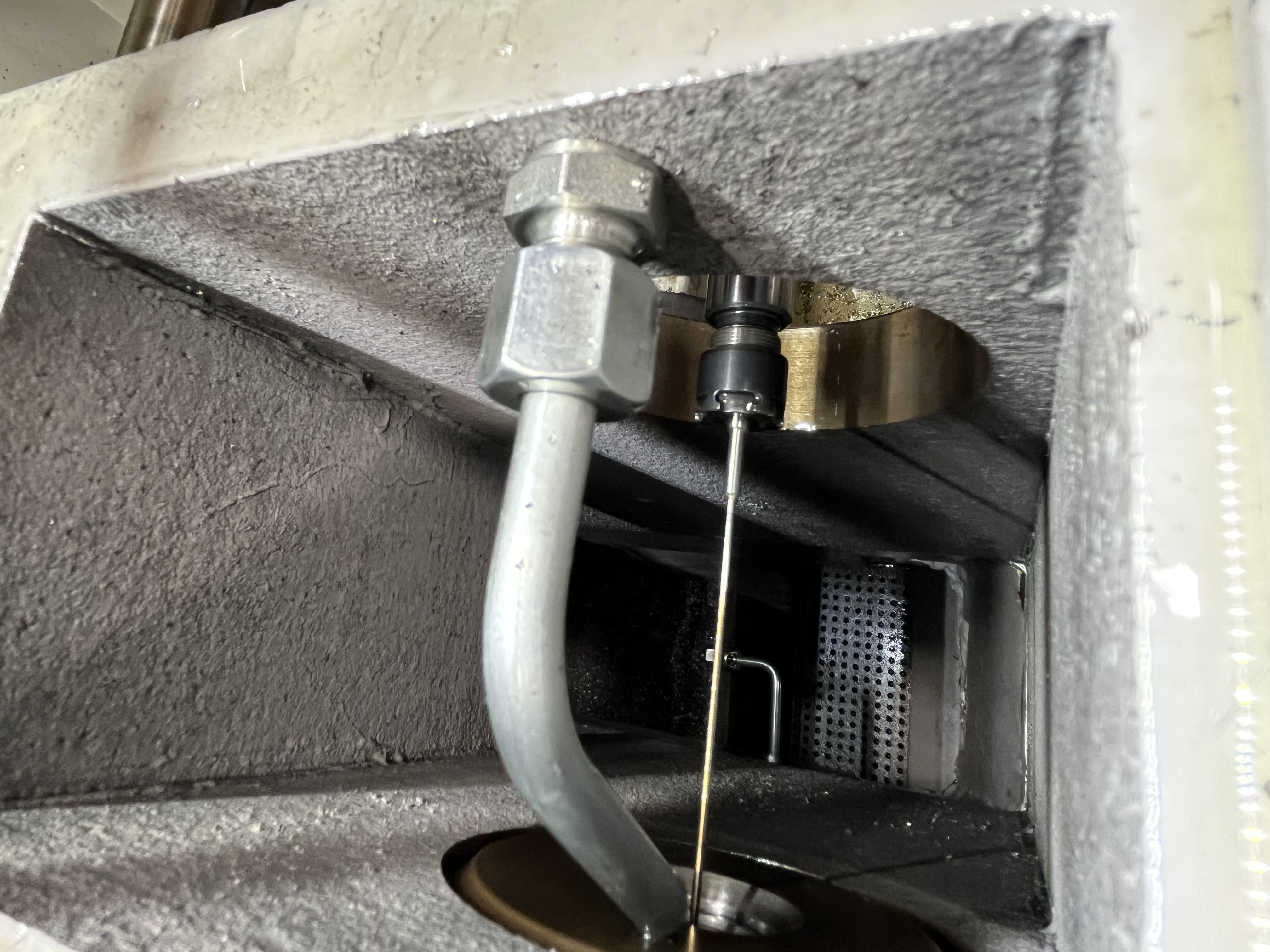
I have broken more gun drills than I care to count. Every one of those breakages happened inside the hole where I could not see it coming. That is what drove me to build a real monitoring strategy — not just watching a spindle load bar on the control, but layering multiple signals so I catch wear, chip packing, and material anomalies before they snap the tool. Here is what I have settled on after years of testing different approaches.
Why Monitoring Matters More in Deep Hole Drilling Than Conventional
In conventional drilling, you can hear the tool start to struggle. The cutters are visible at the spindle face, the chips fly out freely, and you have enough rigidity and short hole depth that a worn tool still finishes the hole. You change the tool when the surface finish degrades or the burr gets too big. It is a forgiving process.
Deep hole drilling is the opposite. The cutting edge disappears into the bore within the first few diameter depths. You cannot hear the difference between normal cutting and a tool that is about to fail because the coolant flow and the length of the drill tube dampen the acoustic signature. Chips travel six, twelve, or twenty-four inches before they exit. By the time you see a coolant pressure drop or a surface finish change, the tool has already taken damage. I have pulled drills with chips packed so tight that the coolant could not push through, and I only caught it because the spindle load hit 180% and tripped the stop.
The economics are different too. A broken gun drill in a 24-inch-deep hole in a titanium aerospace part means a scrapped forging worth thousands of dollars and a week of lost machine time while you extract the broken tool. In conventional drilling, a broken drill means a new drill and five minutes of setup. That risk gap is why I spend time on monitoring that most conventional shops would consider overkill.
Spindle Load Monitoring — The Workhorse
Spindle load monitoring is the foundation of every system I run. The CNC control reads the spindle drive current and converts it to a percentage of the drive rating. The signal is already there in every machine built after 2005. You just have to configure the thresholds and learn to read the patterns.
A normal load curve starts low at entry, climbs to a steady state in the first three to five diameter depths, then stays flat through the rest of the hole. The steady-state value is your baseline. On a fresh tool cutting 4140 steel at recommended parameters, I see about 35-45% of drive capacity. The curve looks like a flat line with a tiny positive slope — 0.5-1% increase from mid-hole to full depth from the friction of the drill bushings and the coolant back pressure.
Problem patterns tell a different story. Here is how I interpret what I see on the spindle load display:
| Load Pattern | What It Looks Like | Probable Cause | What I Do |
|---|---|---|---|
| Normal | Flat line at 35-45%, steady through full depth | Tool cutting properly | Nothing — continue production |
| Worn tool | Gradual upward slope over multiple holes, 1-2% increase per 20 parts | Cutting edge dulling, increasing friction | Change tool when slope steepens past 2% per 10 parts |
| Chip packing | Sudden 30-60% spike over 2-5 seconds, stays high | Chips trapped between drill body and bore wall | Retract immediately, flush chips, check coolant flow |
| Hard spot | Sharp 50-80% spike that drops back to baseline within 1 second | Localized material hardness variation or inclusion | Continue if drill survives the spike; inspect edge at end of hole |
The rate-of-change parameter is more important than the absolute value. I set the control to watch for a 10% increase over a 2-second window and trip an alarm before the absolute threshold is reached. This catches chip packing faster than a fixed percentage alarm because the load jumps long before it hits the 150% stop threshold.
For a deeper breakdown of how I set up load monitoring thresholds, see my article on tool load monitoring.
Acoustic Emission Sensors — The Early Warning System
Spindle load catches established problems. Acoustic emission catches the problems before they become load events.
AE sensors mount on the spindle housing or the drill head support. They detect high-frequency stress waves — in the 100 kHz to 1 MHz range — that travel through the tool and the workpiece material as the cutting edge fractures, chips rub against the bore wall, or a carbide grain pulls out of the cutting edge. These stress waves travel faster than the load change propagates through the drive train.
I started testing AE sensors about three years ago on a particularly troublesome Inconel 718 job. The load monitoring was catching breakages, but I was still losing tools to microchipping that did not show up on the spindle load until the chip had grown large enough to increase cutting forces. The AE signal picked up the microchipping events consistently — a burst of energy at 200-400 kHz that corresponded to the fracture event. I could hear the tool degrading long before the load meter moved.
The challenge with AE is separating the signal from the noise. Coolant flow, the high-pressure pump, and mechanical vibrations from the spindle all produce acoustic energy that can mask the tool wear signal. I use a band-pass filter tuned to the frequency range where cutting edge fracture events occur. I also set a threshold that ignores the continuous AE level and only triggers on transient bursts above a configurable amplitude. The background coolant noise is continuous; tool fracture events are impulsive. That distinction is the key to making AE work.
AE sensors also detect the onset of built-up edge formation, which spindle load misses entirely. BUE generates a characteristic low-amplitude, high-frequency chatter in the AE signal that appears five to ten seconds before the load starts to climb. On aluminum and low-carbon steel jobs, the AE signal has saved me from scrapping parts by catching BUE formation early enough to adjust the coolant concentration or increase the cutting speed.
Coolant Pressure Trending as an Indirect Wear Indicator
I add coolant pressure trending to every monitoring system I set up, even though it is not a direct wear measurement. The pressure tells me about the condition of the coolant path through the tool, and that path changes as the tool wears.
A new gun drill has a clean coolant bore and sharp clearances at the cutting edge. Coolant flows freely through the tip, exits at the cutting edge, and returns through the flute carrying chips. I record a baseline pressure reading at the gauge block near the spindle nose — typically 800-1000 psi for a 0.375-inch gun drill operating at standard parameters.
As the tool wears, three things happen to the coolant pressure:
- The edge clearance wears down, reducing the gap at the cutting edge where coolant exits. Pressure increases by 50-150 psi over the life of the tool.
- Chip packing restricts the return path in the flute. Pressure fluctuates erratically up and down as chips alternately block and clear the passage.
- A crack in the carbide tip or a worn brazed joint leaks coolant internally. The pressure drops suddenly — 200-300 psi in under a second. This is usually the last warning before the tip separates.
I trend the baseline pressure shift across multiple holes, not within a single cycle. A gradual 50-100 psi increase over 50 holes is normal tool wear. A 200-psi increase in ten holes means chip packing is getting worse, usually because the chip breaker geometry is wrong for the material. A sudden pressure drop means the tool is damaged and needs immediate replacement.
Setting Up Alarm Thresholds
Not all monitoring methods are equal. I use a combination because each one covers a blind spot in the others. Here is how I rank the methods I have tested:
| Monitoring Method | What It Detects Best | Typical Cost | Reliability | My Recommendation |
|---|---|---|---|---|
| Spindle load | Chip packing, hard spots, gross tool wear | Free (built into CNC) | High | Always use — no excuse not to |
| Acoustic emission | Microchipping, BUE onset, edge fracture | $2,000-5,000 per channel | Medium — requires tuning | Use on hard alloys and high-value parts |
| Coolant pressure trending | Coolant path restriction, tip damage, chip packing | $500-1,500 for transducer + display | Medium-high | Add to every deep hole machine |
| Vibration (accelerometer) | Spindle bearing wear, tool holder runout, resonance | $300-800 per sensor | Medium — affected by process noise | Good for machine health, not tool wear specifically |
| Temperature (thermocouple at drill bushing) | Gross friction, bushing wear, coolant failure | $200-500 | Low — slow response | Niche use, not my primary method |
| Motor current (PLC-based) | Same as spindle load, separate from CNC | $1,000-3,000 for CT + module | High | Redundant if CNC load monitoring is available |
I set spindle load as the primary alarm and stop source because it is free and reliable. I use AE as a secondary early warning on high-value jobs. I trend coolant pressure on every machine and flag any shift beyond 15% from baseline. The combination catches tool wear, chip packing, coolant failure, and material problems with no single point of failure.
The thresholds I start with:
- Spindle load alarm: 120% of baseline, with a rate-of-change trigger at 10% per 2 seconds
- Spindle load stop: 150% of baseline for general steels, 130% for nickel alloys and titanium
- AE: Impulsive bursts above 60% of the maximum signal observed during a fresh-tool test cut
- Coolant pressure: Alarm at 15% above or below the rolling average over the last 20 holes
The coolant pressure alarm at 15% below baseline is the one that catches the most unexpected failures. A pressure drop does not happen gradually in my experience — it is sudden and it means the tip is cracked. I treat any pressure drop over 10% as a stop-and-inspect event.
Integrating Monitoring Into Production
The technical setup is only half the work. The other half is training the operators to trust the system and respond correctly.
On my production lines, the monitoring system pushes alerts to a display mounted at the machine control. Green means normal operation. Yellow means an alarm threshold has been crossed — the operator acknowledges the alert and inspects the tool at the next tool change opportunity. Red means the machine has stopped on a fault condition, and the operator follows a checklist that starts with retracting the tool and inspecting the cutting edge.
I also log every monitoring event to a database. The log records the time, the machine, the tool ID, the material, the hole depth at the event, and the values of all monitoring signals at the moment of the event. Over the course of a production run, these logs build a tool wear profile for each combination of tool geometry, material, and parameter set. I use the logs to adjust the alarm thresholds for the next run and to identify tools that are failing earlier than expected.
The biggest mistake I see shops make is setting the thresholds once and never touching them again. Tool wear patterns change with batch-to-batch material variation, coolant concentration shifts, and ambient temperature changes. I review the monitoring logs weekly and adjust thresholds as the data accumulates. If the average tool life shifts from 150 parts to 120 parts, something has changed in the process, and the alarm thresholds need to reflect the new normal.
For more on recognizing specific wear patterns on the tool itself, see my guide on gun drill tool wear patterns.
Key Takeaways
- Spindle load monitoring is the baseline — it is free, built into every modern CNC, and catches chip packing and hard spots reliably if you configure the rate-of-change trigger
- Acoustic emission sensors catch microchipping and edge fracture events that spindle load misses entirely, but they require tuning to filter out coolant and vibration noise
- Coolant pressure trending is the most underused monitoring method; a sudden pressure drop means a cracked tip, and a steady drift means normal wear
- Layer multiple monitoring methods to cover blind spots — no single signal catches everything
- Set rate-of-change alarms alongside fixed percentage thresholds; the rate trigger catches chip packing faster
- Log every monitoring event and review the data weekly — tool wear patterns change as the process drifts
- Train operators to trust the alarms and follow a stop-inspect-resume checklist rather than overrides