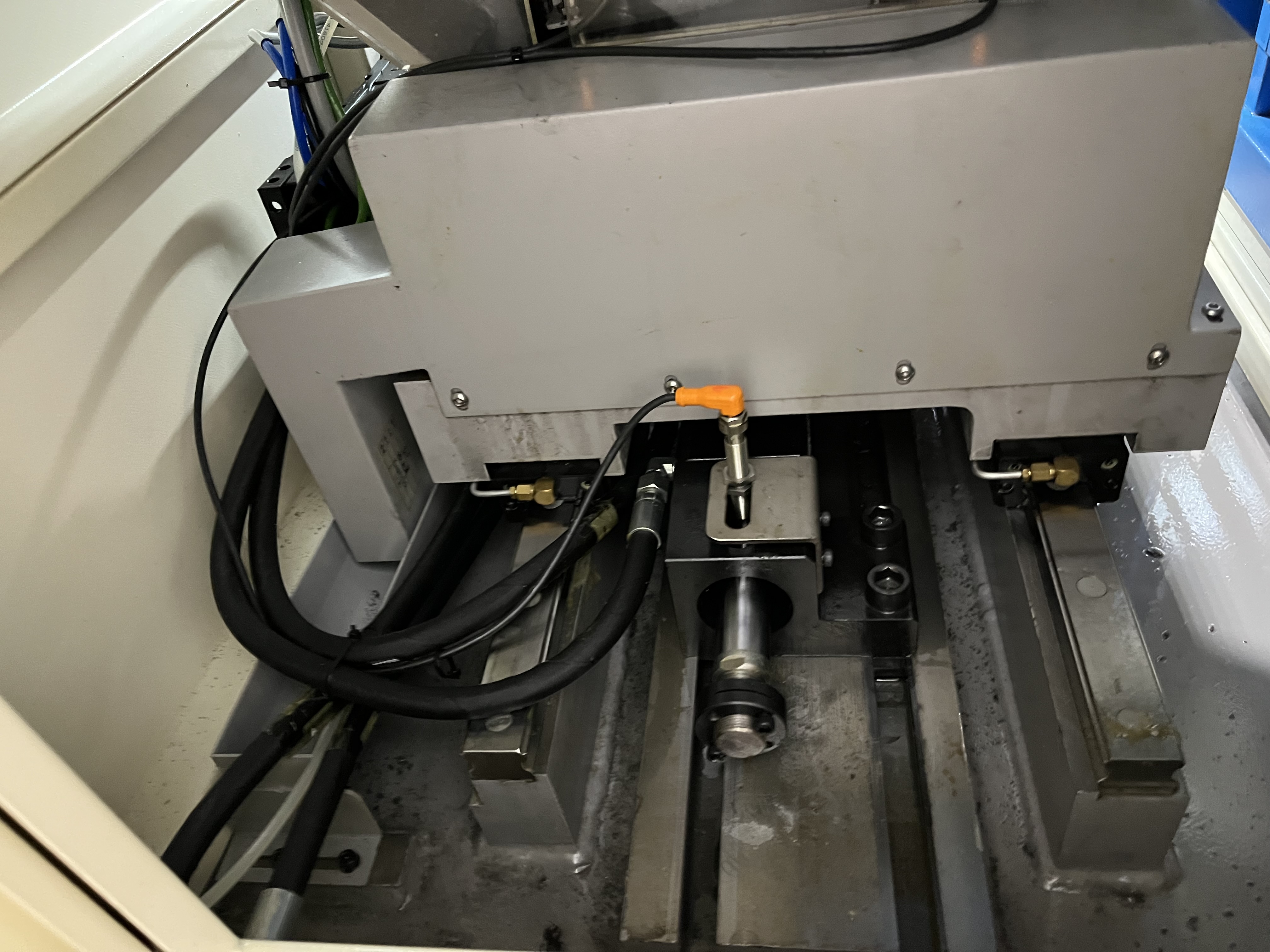
Spindle torque limits protect the drill from overload. When the torque exceeds the limit, the spindle stops. This prevents the drill from twisting apart under excessive load.
I have seen gun drills snap at torque loads just 200 percent above the normal cutting level. A torque limit catches the overload long before that point. Here is how I set up and manage torque limits on my machines for deep hole drilling operations.
Setting the Initial Torque Limit
I set the torque limit based on the baseline torque measured during the first cycle with a new tool. I record the steady-state torque during the cut and set the limit at 150 percent of that baseline. This gives enough headroom for normal variations while protecting the tool from catastrophic loads.
The torque limit must be high enough to allow normal cutting through material variations. A hard spot in the material can cause a temporary torque spike of 120-130 percent of baseline. The limit at 150 percent allows for these variations without nuisance stops.
The limit must also be low enough to stop the drill before it breaks. A drill that is about to fail typically shows a torque increase of 200-300 percent before fracture. The 150 percent limit catches the problem well before the torque reaches the failure point.
Torque Limits by Drill Diameter and Material
Different drill diameters and materials require different torque limit strategies. Smaller drills are more sensitive to overload and need tighter limits. Here is the table I use as a starting point:
| Drill Diameter | Material | Baseline Torque (est.) | Torque Limit Setting | Feed Reduction Threshold |
|---|---|---|---|---|
| 4-6 mm | Low carbon steel | 0.5-1.5 Nm | 120% of baseline | 110% of baseline |
| 4-6 mm | Alloy steel (4140) | 1.0-2.5 Nm | 120% of baseline | 110% of baseline |
| 6-10 mm | Low carbon steel | 2.0-5.0 Nm | 130% of baseline | 115% of baseline |
| 6-10 mm | Stainless steel (316) | 3.0-7.0 Nm | 130% of baseline | 115% of baseline |
| 10-16 mm | Low carbon steel | 5.0-12.0 Nm | 150% of baseline | 120% of baseline |
| 10-16 mm | Alloy steel (4340) | 8.0-18.0 Nm | 150% of baseline | 120% of baseline |
| 16-25 mm | Alloy steel | 12.0-30.0 Nm | 150% of baseline | 125% of baseline |
| 16-25 mm | Cast iron | 8.0-20.0 Nm | 150% of baseline | 120% of baseline |
| 4-10 mm | Titanium (Ti-6Al-4V) | 3.0-8.0 Nm | 120% of baseline | 110% of baseline |
| 10-20 mm | Aluminum (6061) | 1.0-4.0 Nm | 150% of baseline | 120% of baseline |
I adjust these values based on actual chip formation and tool life data from the first few parts. The baseline torque is measured during steady-state cutting after the initial entry, not during the first engagement where the torque naturally spikes higher.
Configuring the CNC Control
I set the limit in the CNC control using the torque limit parameter for the spindle drive. Most controls monitor the drive current and compare it to the programmed limit. The control can act in different ways when the limit is reached.
My preferred configuration uses a two-stage response:
- First stage: The control reduces the feed rate to 50 percent and triggers an alarm
- Second stage: If the torque stays above the limit for more than 0.5 seconds, the spindle stops and the tool retracts
This staged approach prevents nuisance stops from brief spikes while still providing full protection. A hard spot in 316 stainless might spike the torque for 0.2 seconds then drop back. A full stop would waste time and risk tool damage from the sudden reversal.
If the torque limit is reached during a cycle and the spindle stops, the operator investigates the cause before restarting. I train my operators to check for chip packing, coolant issues, and hard spots before re-entering the hole. A restart without investigation risks breaking the tool on the next attempt.
Torque Monitoring and Response Procedure
When the torque limit triggers, I follow a specific response procedure. Here is what I do step by step:
| Trigger Condition | Likely Cause | Immediate Action | Follow-up |
|---|---|---|---|
| Torque exceeds 120% of baseline | Chip packing or material hard spot | Reduce feed by 20% | Check coolant pressure and chip shape |
| Torque exceeds 150% of baseline | Tool overload or drill wear | Stop the spindle, retract tool | Inspect cutting edge, check for damage |
| Torque drops suddenly by more than 30% | Tool breakage or chipped edge | Emergency stop | Remove broken tool, inspect hole |
| Torque increases gradually over several holes | Normal tool wear | No action needed | Plan for tool change at expected life |
| Torque spikes during entry | Misaligned guide bushing or hard spot | Reduce entry feed | Check bushing alignment and material hardness |
I keep a log of every torque limit event. If I see the same type of event recurring, I look for a pattern. Repeated chip packing events might mean the coolant pressure is dropping during the cycle. Repeated entry spikes might mean the guide bushing is worn. The log turns random failures into fixable problems.
Adjusting Torque Limits for Tool Wear
The torque limit should be adjusted as the tool wears. A worn tool requires more torque to cut because the cutting edge is dull and the drill body has more friction in the hole. I increase the limit by 10 percent over the tool life to account for wear.
I use a stepped approach:
- Start at 150 percent for a new tool
- Increase to 155 percent at 30 percent of tool life
- Increase to 160 percent at 60 percent of tool life
- Replace the tool when the baseline torque increases by 20 percent
If the tool reaches the torque limit before the expected tool life, something else is wrong. I stop and investigate rather than just raising the limit further. Common causes are material hardness variations, coolant problems, or incorrect parameters. I have traced several recurring breakage problems back to a coolant pump that was losing pressure after 30 minutes of run time.
Monitoring Response in Production
For high-volume production, I use trend monitoring alongside the torque limit. The control tracks the baseline torque over multiple cycles and alerts me when the trend starts rising. A gradual increase over 10 holes is normal tool wear. A sudden increase in one cycle is a problem that needs investigation.
I set the alarm threshold at a 20 percent increase from the running average. If the torque jumps by 20 percent between two consecutive holes, the control flags the cycle for review. This catches chip packing and coolant problems before they reach the torque limit.
For more details on tool protection strategies, see my guide on tool load monitoring for deep hole drilling. The combination of torque limits and load monitoring covers both sudden overloads and gradual wear trends.
Key Takeaways
- Set torque limits at 150 percent of baseline for standard materials but tighten to 120 percent for small diameters under 6mm
- Use staged response — feed reduction first, then spindle stop — to avoid nuisance stops from brief torque spikes
- Adjust the limit upward by 10 percent over the tool life to account for wear
- Small-diameter drills under 6mm require tighter torque limits because they twist off at lower overload factors
- Investigate the root cause if the limit is reached prematurely — do not just raise the limit
- Different workpiece materials require different torque limit strategies; titanium and stainless steel need tighter limits than carbon steel
- Keep a torque event log to identify recurring patterns that indicate machine or process problems
- Torque limits work best alongside tool load monitoring for complete protection