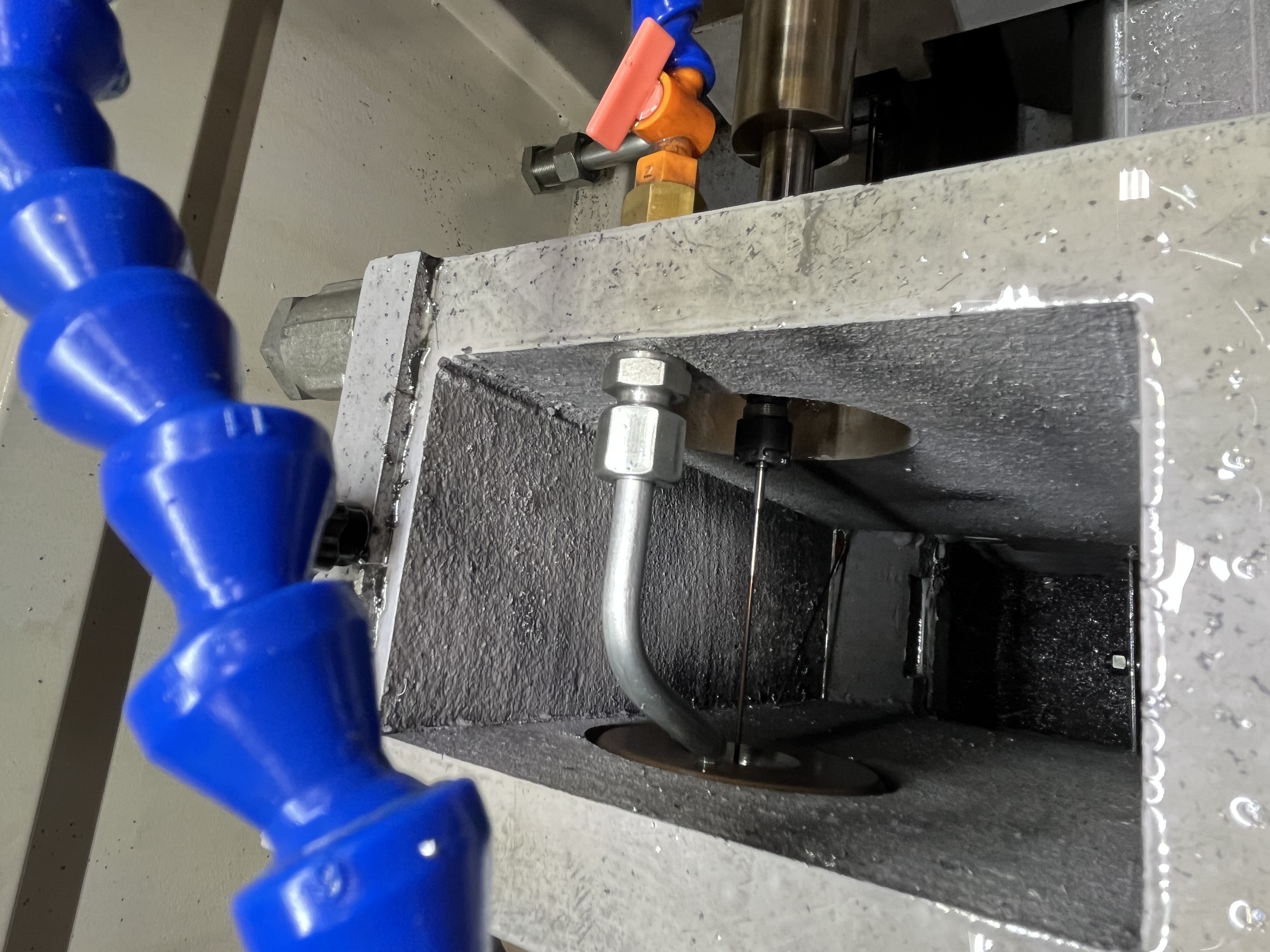
A customer sent a print for a hydraulic cylinder barrel. The print called for a 100mm bore through 3 meters of barrel with a surface finish of Ra 0.2um as-drilled, with no honing allowed. I looked at that print for a solid five minutes before I picked up the phone. I checked it twice to make sure I was reading it correctly. The no-honing note was circled in red with an exclamation mark. Someone at the customer had already flagged this as a critical requirement.
Ra 0.2um as-drilled from a BTA process is not realistic. I knew this before I made the call. The best I have ever seen from a well-tuned BTA head on a good day with consistent material is Ra 0.6um. Typical production runs land between Ra 0.8um and Ra 1.6um depending on the material and the feed rate. I knew immediately that the engineer who wrote this spec either did not understand the BTA process or had copied the number from a different operation.
The print also specified a straightness tolerance of 0.05mm per meter. That is achievable with BTA drilling on a 3-meter barrel, but it requires a machine in good alignment and stable material. The combination of that straightness with the surface finish told me the engineer had designed this around a honing operation and then removed the honing step without adjusting the specs. I have seen this exact pattern half a dozen times in my career.
Why Ra 0.2um Is Not Achievable with BTA Drilling
BTA drilling uses single or multi-edge cutting heads with guide pads. The guide pads burnish the bore surface as the head passes through. That burnishing action produces a surface finish in the range of Ra 0.6um to Ra 1.6um under normal conditions. To get down to Ra 0.2um, you need a finishing process like honing, roller burnishing, or fine boring. I have never seen a BTA head produce a consistent Ra 0.2um finish on a 3-meter barrel regardless of the parameters used.
The feed rate directly affects the surface finish in BTA drilling. Each revolution of the head leaves a feed mark. The depth of that mark is determined by the feed per revolution and the tool geometry. At a feed rate of 0.1mm per revolution, the theoretical peak-to-valley height is about 0.8um Ra in typical steel. To get down to 0.2um Ra, you would need a feed rate so low that the cutting edge would rub instead of cut. Rubbing creates heat, work hardening, and poor surface integrity.
Here is a comparison of surface finishes I have measured across different processes on hydraulic cylinder barrels:
| Process | Typical Ra Range (um) | Typical Application |
|---|---|---|
| BTA drilling (production) | 0.8 - 1.6 | As-drilled for subsequent honing |
| BTA drilling (best case) | 0.6 - 0.8 | Light finishing pass with wiper inserts |
| Single-pass honing | 0.2 - 0.4 | Hydraulic cylinder finish |
| Multi-pass honing | 0.05 - 0.2 | Precision hydraulic applications |
| Roller burnishing | 0.1 - 0.4 | Surface finish improvement |
| Fine boring | 0.4 - 0.8 | Secondary machining operation |
| Gun drilling | 0.4 - 1.2 | Small diameter deep holes |
I have run hundreds of BTA jobs over the years. Not one of them came out at Ra 0.2um as-drilled. The physics of the cutting process does not allow it. The feed marks from the cutting edge alone produce a theoretical minimum finish that is higher than 0.2um. Even with a wiper insert and reduced feed, the best I have measured is Ra 0.6um on a 1045 steel barrel. The surface finish also degrades as the tool wears, so even if the first barrel measures Ra 0.6um, the 50th barrel will measure higher. That is the nature of the process.
How Surface Finish Relates to Feed Rate
The relationship between feed rate and surface finish in BTA drilling is well understood. The theoretical surface roughness from feed marks alone follows a formula based on the feed per revolution and the tool nose radius. For a BTA head with a typical nose radius, a feed of 0.08mm per revolution gives a theoretical Ra of about 0.8um. To reach Ra 0.2um, you would need a feed rate of about 0.02mm per revolution. At that feed rate, the cutting edge does not cut effectively. It rubs against the material, generates excessive heat, and causes work hardening. The drill will not last through a single 3-meter barrel at that feed rate.
I ran a test once to prove this point. I programmed a BTA head at the feed rate required for Ra 0.2um and ran it through a 1-meter test barrel. The tool lasted 400mm before the edge broke down from rubbing. The surface finish at the entry was Ra 0.4um, but it degraded to Ra 1.2um by the time the tool failed. That test cost me a drill head but it confirmed what I already knew from the theory. There is no shortcut to the physics of the cutting process.
I now use this test data when I talk to customers about surface finish specs. I can tell them exactly what feed rate produces what finish and what the trade-offs are. The data makes the conversation concrete. A customer who sees a test result is more convinced than one who hears an opinion.
The Phone Call
I called the customer and asked to speak with the engineer who designed the part. The receptionist put me through to his voicemail. I left a message explaining that I had a question about the surface finish spec on the barrel print and that I had a solution to propose. He called back within the hour. I appreciated that. A lot of engineers ignore calls from suppliers once the print is out, especially when the call is about a potential problem with their design.
The engineer who designed the part was new to deep hole drilling. His background was in precision machining of small components, not in deep hole drilling of large cylinders. He told me he had copied the surface finish spec from a honing operation on a different part — a small servo cylinder they manufactured. He assumed the BTA process could achieve a similar finish because both processes produce a smooth bore. I have heard this assumption more times than I can count.
I explained the difference between the two processes. A honing stone contacts the full bore surface and averages out the peaks and valleys. It is an averaging process that removes material uniformly across the surface. A BTA drill head cuts with a single point and leaves feed marks that are inherent to the process. No amount of tuning will eliminate those feed marks completely. You can reduce them with lower feed rates and wiper inserts, but you cannot eliminate them. I also explained that the guide pads in BTA drilling burnish the surface but do not remove material. They smooth the peaks but the feed mark pattern remains.
He listened carefully. He asked good questions about what Ra values I typically see and what the process capability was for my machine on 3-meter barrels. I told him I could guarantee Ra 1.6um as-drilled with a 0.3mm honing allowance. That would give his honing operation clean material to work with and he could achieve Ra 0.2um after honing. I also explained that the honing allowance would let them correct any minor straightness deviations.
The Revised Print and the Production Run
The customer changed the spec to Ra 1.6um as-drilled with a honing allowance of 0.3mm on the diameter. They sent me a revised print within two days of our call. The engineer had updated the drawing notes to reference both the drilling spec and the subsequent honing spec separately. That is exactly what I had recommended. They also reduced the straightness spec to 0.1mm per meter, which was more realistic for a 3-meter barrel. The honing operation would correct any minor straightness deviations and bring the final bore to their original spec.
The job went smoothly from start to finish. I drilled all 50 barrels at Ra 1.2um average surface finish. The setup took one day, the production run took five days, and the inspection passed on the first attempt. I sent the QA report to the engineer along with the parts. The best barrel measured Ra 0.8um and the worst was Ra 1.4um. All were well within the revised spec. The customer honed them down to Ra 0.2um on their end and reported zero issues. The engineer sent me a note afterward saying he appreciated the call and that he had updated his design standards to include separate specs for drilling and honing.
I have seen this pattern repeat with new engineers. They come from other manufacturing disciplines and assume deep hole drilling follows the same rules as turning or milling. It does not. The depth-to-diameter ratio changes everything. A 30-to-1 ratio bore like this one behaves differently than a 3-to-1 ratio bore. Chip evacuation, coolant flow, tool deflection, and surface finish all behave differently at extreme depth ratios. I have a standard explanation I give to new engineers now. I explain that a deep hole is not a long shallow hole. The physics changes when the bore depth exceeds 10 times the diameter.
I learned something important from this experience. A customer engineer who makes a mistake on a print is not failing. They are designing outside their area of expertise. My job is to help them get the part they need, not to make them feel bad about a wrong number. I kept the conversation professional and focused on the solution. That approach turned a potential conflict into a long-term partnership.
The relationship I built with that engineer has paid off several times since. He now calls me before he finalizes a print to ask what tolerances are achievable. That saves both of us time and prevents spec issues before they reach the quoting stage. I consider that relationship as valuable as any machine in my shop.
How I Handle Questionable Specs Now
I have developed a standard process for handling prints that do not make sense. First, I flag any spec that I know is outside my process capability. I maintain a process capability chart for each machine that lists achievable tolerances for diameter, straightness, and surface finish at different bore depths and material types. I update this chart every quarter based on actual production data.
Second, I call the customer engineer directly, not the purchasing department. Purchasing cannot change a spec. The engineer can. I have learned to go straight to the person who designed the part. I introduce myself, explain that I have a question about the print, and ask if they have a few minutes to talk through it.
Third, I offer an alternative spec that I can guarantee. I do not just say a spec is wrong. I say what I can achieve and what the customer needs to change to get their desired result. I present it as a solution, not a complaint. This approach has worked every time I have used it because it helps the engineer get what they actually need rather than defending a number they copied from another print.
Fourth, I document the conversation in an email after the call. I summarize what we agreed to and attach a marked-up print. I ask the engineer to reply with approval before I start cutting chips. This has saved me from misunderstandings more than once, especially when the purchasing department tries to hold me to the original print specs.
Fifth, I follow up with a thank-you note after the job ships. A brief email saying the parts are on the way and that I appreciated the collaboration goes a long way. Engineers remember who made their job easier and who gave them a hard time. I want to be the first kind.
This five-step process has saved me from at least a dozen bad jobs over the years. Every time I skip a step, I regret it.
Key Takeaways
- Question specs that do not match your process capability. The cost of a phone call is nothing compared to the cost of scrapped parts.
- Be polite but direct when you tell a customer their spec is wrong. Most engineers appreciate the feedback once they understand the reasoning.
- Have data ready when you make the call. I keep a process capability table for each machine so I can quote realistic numbers on the spot.
- Experienced engineers have been through this before and will trust your judgment. New engineers need explanation and evidence.
- A revised spec that works is better than an original spec that fails every inspection.
- Build relationships with customer engineers. The next time they design a part, they will call you first to ask what is achievable.
- Document every spec change in writing. I sent a revised print mark-up and got a signed approval before cutting the first chip.
- Offer solutions, not complaints. A customer who hears what they can have is happier than one who hears what they cannot have.