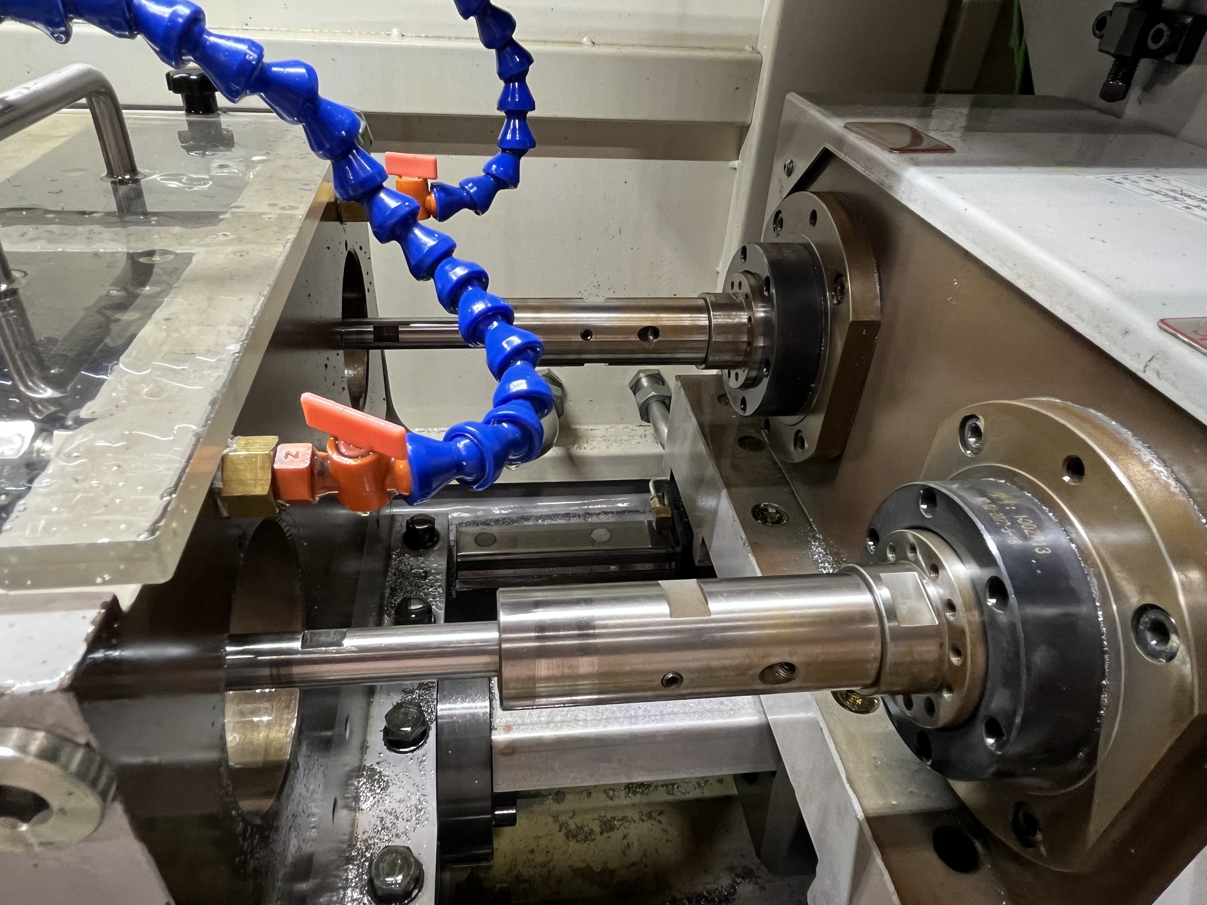
Why Accelerometer Monitoring Matters
A spindle failure on a deep hole drilling machine stops everything. The machine is down for days while the spindle is rebuilt or replaced. I use accelerometer-based vibration monitoring to detect bearing defects months before they cause failure, so I can schedule repairs during planned downtime.
The accelerometer system cost is about 2000-5000 USD for a single machine. The value is in preventing unexpected spindle failures that cause extended downtime. A single emergency spindle replacement can cost 15,000-30,000 USD in parts and labor plus lost production time.
Accelerometer Types Comparison
I have used three main accelerometer types for spindle monitoring. Each has its place depending on the application:
| Type | Frequency Range | Sensitivity | Temperature Limit | Cost | Best For |
|---|---|---|---|---|---|
| ICP/IEPE piezoelectric | 0.5 Hz - 10 kHz | 10-100 mV/g | 125-175 C | 300-800 USD | General spindle vibration, bearing defects |
| Charge mode piezoelectric | 0.1 Hz - 10 kHz | Varies (pC/g) | Up to 650 C | 500-1500 USD + amp | High-temp spindles, research |
| MEMS capacitive | 0 Hz (DC) - 2 kHz | 6.75-1000 mV/g | Up to 125 C | 50-200 USD | Low-speed spindles, tilt monitoring |
For standard deep hole drilling spindles running at 1500-6000 RPM, I use ICP accelerometers with 100 mV/g sensitivity. This gives the best balance of low-noise performance and frequency range for bearing defect detection. The annual safety audit checklist covers the inspection intervals that go with a vibration monitoring program.
Accelerometer Placement Guide
I mount the accelerometer on the spindle housing near the front bearing. The front bearing carries the highest load and fails first in most deep hole drilling applications. The mounting surface must be clean, flat, and free of paint. I use a stud mount with a thin layer of silicone grease for the best frequency response.
For through-hole drilling on BTA machines, I also place a secondary accelerometer on the tool bushing holder. The bushing holder vibration reveals tool deflection and guide pad wear before they affect hole quality.
| Mounting Location | What It Detects | Recommended? |
|---|---|---|
| Spindle housing, front bearing zone | Bearing defects (BPFO, BPFI, BSF) | Primary (always) |
| Spindle housing, rear bearing zone | Rear bearing defects, motor coupling | Secondary (if accessible) |
| Tool bushing holder | Guide pad wear, tool whip | For BTA/ejector machines |
| Machine base/column | Structural resonance, chatter | For troubleshooting |
| Coolant supply head | Coolant seal wear | For high-pressure systems |
The accelerometer connects to a data collector that displays the vibration spectrum. I set the frequency range to 0-5000 Hz for most spindle bearing analysis. Higher ranges up to 10,000 Hz are needed for ceramic bearing elements.
I collect baseline data when the spindle is new or freshly rebuilt. The baseline establishes normal vibration levels at each spindle speed used in production. I save this data as the reference for all future comparisons.
Bearing Defect Frequencies
Each bearing component produces vibration at a specific frequency that depends on the bearing geometry and spindle speed. The four key defect frequencies are:
| Component | Frequency Calculation | Typical Range at 3000 RPM |
|---|---|---|
| Outer race | BPFO = (N/2) x RPM x (1 - Bd/Pd x cos A) | 200-300 Hz |
| Inner race | BPFI = (N/2) x RPM x (1 + Bd/Pd x cos A) | 300-400 Hz |
| Ball/roller | BSF = (Pd/Bd) x RPM x (1 - (Bd/Pd x cos A)^2) | 400-600 Hz |
| Cage | FTF = (RPM/2) x (1 - Bd/Pd x cos A) | 15-25 Hz |
Where N is the number of rolling elements, Bd is ball diameter, Pd is pitch diameter, and A is the contact angle.
I enter these formulas into the data collector once for each bearing type. The collector automatically marks the defect frequencies on the spectrum display. A peak at any of these frequencies indicates a defect in that component.
Diagnosis Chart: Reading the Vibration Spectrum
Here is the diagnosis chart I use when I see specific vibration patterns:
| Spectrum Signature | Likely Problem | Confirmation | Action |
|---|---|---|---|
| Peak at BPFO + harmonics | Outer race defect | Check amplitude trend vs baseline | Plan bearing replacement at 2x baseline |
| Peak at BPFI + sidebands at RPM | Inner race defect | Sideband spacing equals RPM | Schedule replacement at 2.5x baseline |
| Peak at BSF + random impacts | Ball/roller defect | Irregular timing between impacts | Replace bearing within 1 month |
| Peak at FTF + hunting tooth | Cage wear | Irregular low-freq modulation | Immediate replacement risk |
| Broad rise 500-2000 Hz band | Generalized wear or contamination | Check lubricant for debris | Inspect and clean or replace |
| Harmonic peaks at multiples of RPM | Unbalance or misalignment | Check 1x, 2x, 3x RPM peaks | Rebalance or realign spindle |
| Sub-harmonic at 0.5x RPM | Oil whirl (fluid-film bearings) | Only applies to sleeve bearings | Adjust oil temperature/pressure |
A bearing with a defect on the outer race shows a peak at the Outer Race Pass Frequency (BPFO). The amplitude increases as the defect grows. When the amplitude reaches 2 times the baseline, the bearing needs replacement at the next opportunity. At 4 times baseline, replacement is urgent.
Inner race defects show sidebands around the BPFI peak, spaced at the spindle running speed. The sidebands appear because the defect rotates in and out of the load zone. A BPFI peak with strong sidebands indicates an advanced defect.
I pay close attention to the overall vibration level in the 500-2000 Hz band. This range captures the bearing defect frequencies for most spindle bearings used in deep hole drills.
Threshold Setting and Alarm Levels
Setting the right alarm thresholds is critical. Too low and I get false alarms. Too high and I miss developing defects. Here is the system I use based on ISO 10816 guidelines adapted for spindles:
| Severity Level | Velocity (mm/s RMS) | Acceleration (g RMS) | Meaning |
|---|---|---|---|
| Good | Below 1.5 | Below 0.15 | Normal operation, continue monthly checks |
| Warning | 1.5 - 3.5 | 0.15 - 0.5 | Increase monitoring to weekly, investigate cause |
| Alarm | 3.5 - 7.0 | 0.5 - 1.5 | Plan bearing replacement, check within 2 weeks |
| Danger | Above 7.0 | Above 1.5 | Stop machine, replace bearing immediately |
I use the baseline-plus-multiplier method for bearing defect frequencies. A 2x increase over baseline at any defect frequency triggers a warning. A 4x increase triggers immediate action regardless of the absolute level.
Trending and Scheduling
I collect acceleration data monthly for critical spindles and quarterly for standard machines. Each reading is compared to the baseline. Trends are more important than absolute values. A gradual increase over several months indicates progressive bearing wear.
A sudden jump of 2x or more between consecutive readings indicates a spalling defect or a lubrication failure. I stop the machine and inspect the bearing immediately when I see a sudden jump.
I have caught bearing defects 3-6 months before failure using acceleration trending. In one case, a spindle on a high-production BTA machine showed a slow increase in BPFO amplitude over four months. I scheduled the bearing replacement during a holiday shutdown. The bearing was found with a 5 mm spall on the outer race, within 2 weeks of catastrophic failure. The common deep hole drilling problems guide covers additional failure modes to track alongside vibration data.
Common Pitfalls
Accelerometer readings are affected by the spindle speed. I always collect data at the same spindle speed for trend comparisons. A reading at 4000 RPM cannot be compared to a baseline taken at 3000 RPM.
Belt-driven spindles show belt frequencies in the vibration spectrum that can be mistaken for bearing defects. I identify belt frequencies by checking if the frequency changes with belt tension. Belt frequencies disappear when the belt is removed.
Temperature affects accelerometer readings. I let the spindle reach operating temperature before collecting data. A cold spindle has higher vibration amplitudes than a warm spindle due to tighter bearing clearances.
Magnetic mounting bases reduce the effective frequency range by about 30 percent compared to stud mounting. I never use magnetic mounts for bearing analysis above 2000 Hz.
Key Takeaways
- Accelerometer monitoring detects bearing defects 3-6 months before failure.
- Mount the accelerometer near the front bearing on a clean, flat surface with stud mount.
- Calculate defect frequencies from bearing geometry for each bearing type.
- Use the diagnosis chart to identify specific bearing component failures from spectrum signatures.
- Replace bearings when the defect frequency amplitude reaches 2x baseline; act immediately at 4x.
- Collect data at the same spindle speed and operating temperature for consistent trending.
- ICP piezoelectric sensors with 100 mV/g sensitivity are the best choice for standard spindle monitoring.
- Set ISO 10816-based velocity thresholds at 1.5/3.5/7.0 mm/s for warning/alarm/danger levels.