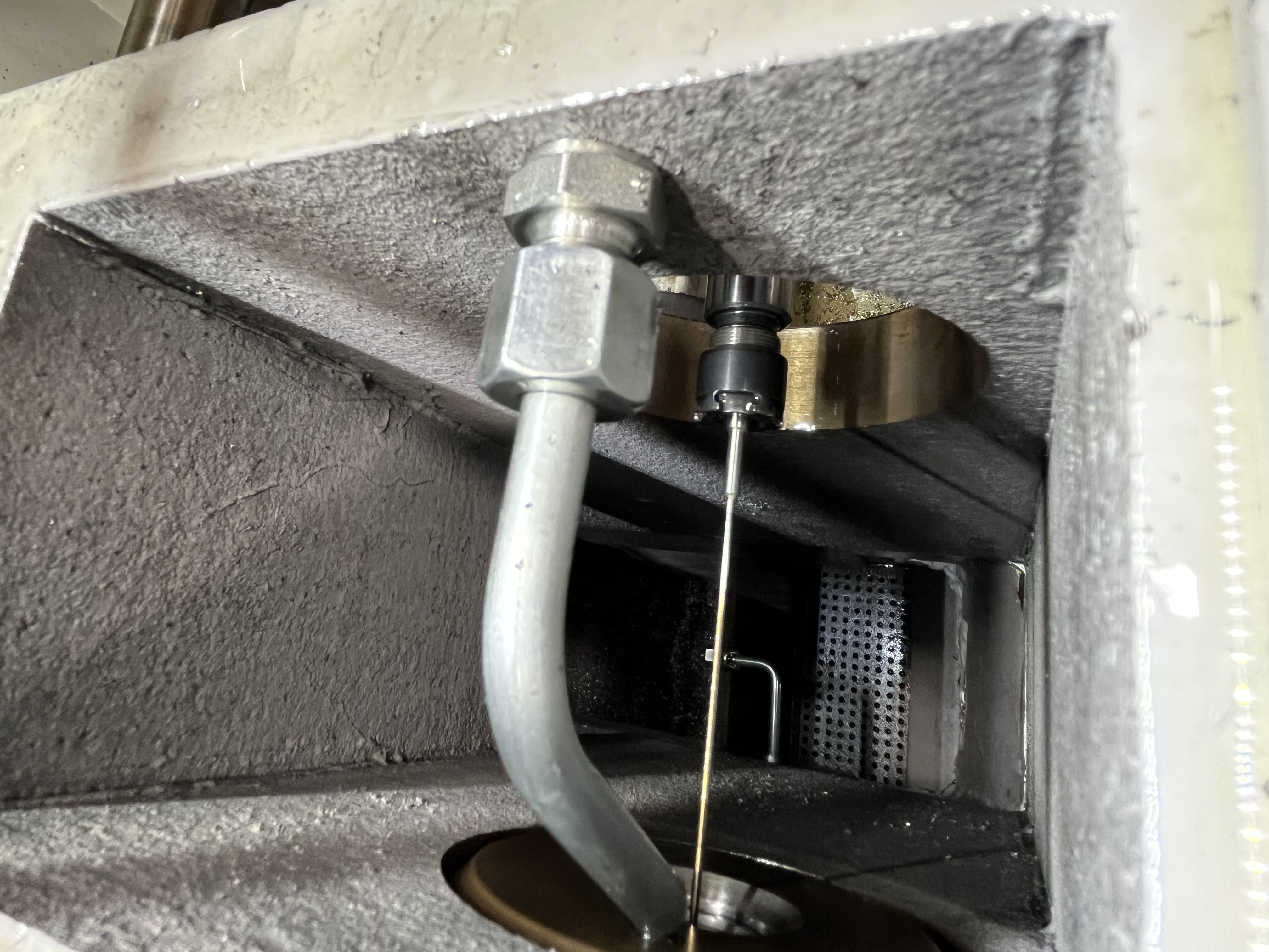
I have spent years running deep hole drilling operations across a wide range of materials, and aluminum consistently surprises newcomers. Steel is forgiving in predictable ways — you manage heat, you manage feed, and the chips mostly cooperate. Aluminum fights you on a different front. The chips are long and stringy, the material wants to weld itself to your tool, and a perfectly sized bore can turn into a scratched mess in seconds. This article covers the three problems I run into most often with aluminum and exactly how I fix each one.
Built-Up Edge Causes and Fixes for Aluminum
Built-up edge (BUE) is the single most common issue I see in aluminum gun-drilling. Aluminum has a low melting point and high ductility, which means the work material can cold-weld onto the cutting edge under the right (or rather, wrong) conditions. Once that welded layer builds up, the effective geometry of the drill changes — the cutting edge becomes dull, thrust forces increase, and the bore surface suffers.
The root cause is almost always a combination of edge temperature and surface affinity. If the cutting edge stays below the re-crystallization temperature of aluminum, the chip material bonds rather than sliding off. I have found that the fix usually comes down to three adjustments:
- Increase surface speed. Higher cutting speeds generate enough frictional heat to keep aluminum above its re-crystallization temperature, preventing the material from sticking. For 6061-T6, I typically run between 300 and 450 SFM. For softer alloys like 1100, I push toward the high end of that range.
- Apply a sulfur-free oil with high extreme-pressure (EP) additives. Aluminum reacts poorly with sulfur-based EP additives — it can cause corrosion and staining. I use a chlorinated or ester-based EP additive instead, which forms a sacrificial film on the cutting edge and prevents metal-to-metal contact.
- Hone the cutting edge. A razor-sharp edge is more prone to micro-chipping, which creates nucleation sites for BUE. A light hone (0.001 to 0.003 inch radius) stabilizes the edge and reduces the tendency for material to weld onto it.
I cover this topic in more depth in my dedicated article on built-up edge in gun-drilling, which goes into the metallurgy behind BUE formation and how to diagnose it from the chip morphology alone.
Chip Packing in Aluminum (Why It Is Different from Steel)
Chip evacuation is the dominant challenge in any deep hole drilling operation, but aluminum makes it uniquely difficult. Steel chips are typically short and segmented — they break into manageable pieces that flush through the chip trough without much fuss. Aluminum chips, especially from the 6000 and 7000 series alloys, are long, continuous, and ductile. They form helical ribbons that can wrap around the drill shank, jam in the chip trough, and eventually pack solid.
The consequences of chip packing are immediate and severe. Once the chip trough is blocked, coolant flow is restricted, the drill starves, and the cutting edge overheats. I have seen packed aluminum chips cause drill breakage within seconds of the first blockage.
Here is what I do differently for aluminum chip control:
- Step-feed drilling. Instead of a continuous feed, I program a peck or step-feed cycle. Even a brief retraction every 3 to 5 diameters breaks the chip into shorter segments and clears the trough.
- Chip breaker geometry. I specify gun-drills with a chip-breaker notch or a modified tip geometry that promotes chip segmentation. Some tool suppliers offer aluminum-specific tip geometries with a wider chip trough and a steeper chip-breaker angle.
- Increase coolant flow rate. Aluminum packs faster than steel, so I run coolant flow at the upper end of the tool manufacturer’s recommendation. For a 10 mm gun-drill, I target a minimum of 150 PSI and verify flow at the drill tip before every job.
If you are new to aluminum gun-drilling, I recommend reading the full overview in my gun-drilling aluminum process guide, which covers machine setup and tool selection in more detail.
Surface Finish Defects Specific to Aluminum
Surface finish problems in aluminum are often the first symptom of a deeper issue. Where a steel bore might show a gradual roughness increase over hours, an aluminum bore can go from mirror-finish to scrap in a single pass. The defects I encounter most are:
Scratches and scoring. These run axially along the bore wall and are almost always caused by trapped chips in the guide pad area. The fix is improved chip evacuation (see the section above) and verifying that the guide pads are not worn.
Smearing. The surface looks burnished rather than cut, with a smeared, smudged appearance. This happens when the workpiece material re-welds to the bore wall behind the cutting edge. I fix this by increasing the coolant concentration (see the next section) and confirming the guide pad clearance angles are adequate.
Chatter marks. Circumferential bands or a regular wavy pattern on the bore wall point to vibration. Aluminum has a lower damping coefficient than steel, so it rings more easily. I reduce the RPM slightly and increase feed per revolution to keep the process stable.
White layer. A thin, hardened, white-etching layer on the bore surface is a sign of thermal damage. This is rare in aluminum compared to steels, but I have seen it in 7075-T6 when coolant pressure was too low. The fix is the same as for BUE — more coolant and higher surface speed to keep the cutting zone temperature in the sweet spot.
Coolant Concentration Adjustments for Aluminum
Coolant chemistry matters more for aluminum than for almost any other material I drill. The wrong concentration can cause staining, poor lubricity, or even gassing at the cutting interface. Here are the guidelines I follow:
- Oil-based coolant. For gun-drilling aluminum, I use a high-viscosity sulfur-free oil (typically 40 to 70 SUS at 100 F). The high viscosity provides the boundary lubrication needed to prevent BUE and smearing.
- Water-soluble coolant. If water-soluble is required (for example, on a multi-purpose machine that also runs steel), I run the concentration at 8 to 12 percent — significantly higher than the 5 to 7 percent I use for steel. The extra concentration improves lubricity and raises the boiling point at the cutting edge.
- pH monitoring. Aluminum is sensitive to alkaline coolants. I keep the pH between 8.0 and 8.5. Above 9.0, the coolant can stain aluminum and reduce tool life. I check pH weekly and adjust with a mild acidic additive if needed.
- Deionized water for mixing. Tap water with high mineral content reacts with aluminum and leaves deposits on the bore surface. I mix coolant with deionized or softened water to avoid this.
Speed and Feed Adjustments to Solve Problems
When a problem appears — BUE, poor finish, or chip packing — my first response is never to change the tool. I adjust cutting parameters first. Aluminum is responsive to parameter changes in ways that steel is not, and a 10 percent change in speed or feed can be the difference between a pass and a reject.
The table below lists the parameters I use as starting points for common aluminum alloys, along with the adjustments I make when specific problems arise.
| Alloy | SFM Range | Feed (IPR) | Notes |
|---|---|---|---|
| 2024-T3 | 250–350 | 0.001–0.002 | Good chip breaking; increase feed if BUE appears |
| 5052-H32 | 300–400 | 0.001–0.003 | Soft alloy; push speed higher for finish |
| 6061-T6 | 300–450 | 0.002–0.004 | Most common alloy; my default starting point |
| 6063-T5 | 300–400 | 0.002–0.004 | Similar to 6061 but softer; watch for smearing |
| 7075-T6 | 200–300 | 0.001–0.002 | Harder; reduce speed to manage heat |
| 1100-O | 350–500 | 0.001–0.002 | Very soft; increase coolant concentration |
| 319 (cast) | 200–300 | 0.002–0.004 | Abrasive; watch tool wear more than BUE |
When I troubleshoot, I follow this sequence:
- If BUE appears: Increase SFM by 10 to 15 percent first. If BUE persists, increase coolant concentration and EP additive level.
- If chips are too long: Reduce feed by 10 percent to encourage chip segmentation. If still stringy, switch to step-feed.
- If surface finish degrades: Check coolant flow at the tip first. If flow is good, increase SFM by 5 to 10 percent and decrease feed by 5 percent.
- If tool squeals or chatters: Reduce RPM by 10 percent and increase feed by 10 percent to stiffen the effective cutting edge engagement.
Problem vs Cause vs Fix Reference Table
| Problem | Likely Cause | Fix |
|---|---|---|
| Built-up edge on cutting edge | Low surface speed or insufficient EP lubrication | Increase SFM; add chlorinated EP additive; hone cutting edge |
| Long stringy chips jamming trough | Ductile chip formation; no chip breaker | Switch to step-feed; specify chip-breaker tip geometry |
| Scratched bore wall | Trapped chips between guide pad and bore | Improve chip evacuation; verify guide pad wear |
| Smear or burnished surface finish | Re-welding behind cutting edge | Increase coolant concentration to 10–12%; verify pad clearance |
| White layer on bore surface | Thermal damage from low coolant pressure | Increase coolant PSI; verify flow at drill tip |
| Chatter marks on bore wall | Vibration due to low damping in aluminum | Reduce RPM 10%; increase feed 10% |
| Coolant staining on aluminum | Alkaline coolant or high mineral content in mix water | Adjust pH to 8.0–8.5; use deionized water |
| Abrasive tool wear (cast alloys) | Silicon content wearing carbide | Consider PCD-tipped drill for high-silicon alloys |
Key Takeaways
- Built-up edge in aluminum is driven by edge temperature and material affinity. Higher surface speed and sulfur-free EP additives are the most effective fixes. Do not overlook edge honing.
- Chip packing is more aggressive in aluminum than in steel because aluminum chips are long and ductile. Step-feed cycles and chip-breaker tip geometries are the most reliable solutions. Dedicated reading on the topic is in my gun-drilling aluminum guide.
- Surface finish defects in aluminum — scratches, smearing, chatter, and white layer — each point to a distinct root cause. Treat the cause, not the symptom.
- Coolant concentration should be 8 to 12 percent for water-soluble systems, with pH tightly controlled between 8.0 and 8.5. Oil-based systems benefit from higher viscosity and sulfur-free formulations.
- Parameter adjustments are the first lever I pull. SFM helps BUE; feed helps chip control; RPM helps chatter. Change one variable at a time and verify the result before making another adjustment.
- For a deeper look at the BUE mechanism and how to diagnose it from visual cues, see the built-up edge article.