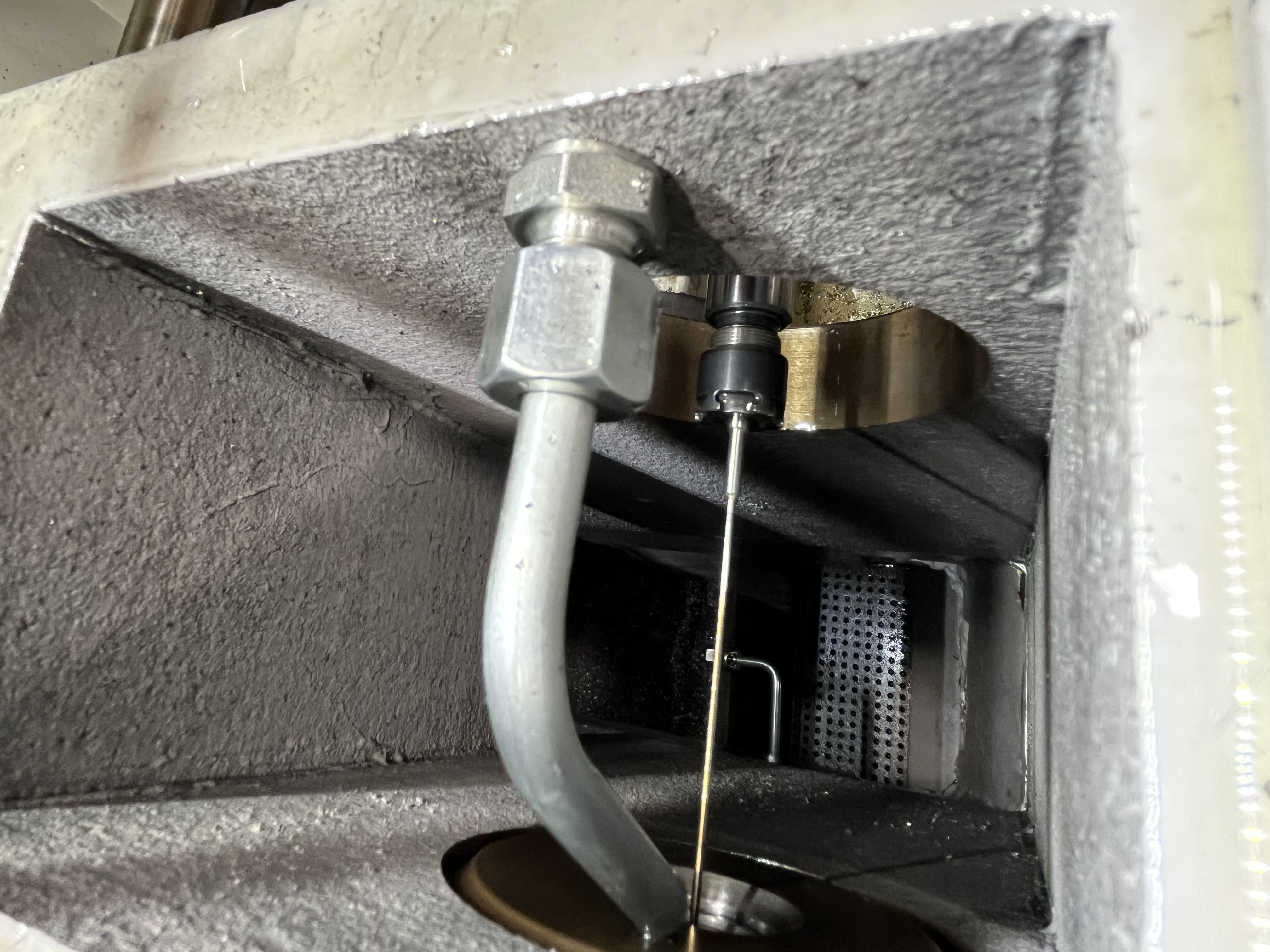
How BTA Machines Differ from Gun Drill Machines for Gun Drilling
I have spent years running gun drills on both dedicated gun drilling machines and BTA machines, and I can tell you they are not the same animal. On a dedicated gun drill machine, everything is optimized for the gun drill’s operating principles: high coolant pressure at moderate volume, steady spindle speeds, and a rigid guide bushing setup that keeps the drill tip centered before it enters the workpiece.
A BTA machine, by contrast, is built around the BTA drilling process. The spindle is designed to handle large-diameter BTA heads with high torque and lower RPM ranges. The coolant system delivers high volume at moderate pressure through a BTA coolant manifold. The chip evacuation path runs through the drill tube instead of along the flute, which changes the entire hydraulic profile of the system.
When you mount a gun drill on a BTA machine, you are forcing a precision tool designed for one set of conditions into a system tuned for something fundamentally different. The result is a set of failure modes that rarely appear on dedicated machines.
Why Breakage Patterns Are Different
I have broken gun drills on dedicated machines before – usually from aggressive feed rates, worn bushings, or interrupted cuts. The breakage tends to be clean: the drill tip fractures at the carbide shank junction, or the chisel edge chips from a hard inclusion. You can usually trace it back to a single overload event.
On a BTA machine, the breakage patterns are messier and harder to diagnose. Here is what I have learned from breaking more gun drills than I care to count on BTA setups:
| Breakage Pattern | Root Cause in BTA Setup |
|---|---|
| Spiral fracture along flute length | Intermittent chip packing inside the BTA chip tube creating hydraulic hammer |
| Tip chipping on exit side | Loss of back pressure when gun drill exits the BTA seal – coolant flow suddenly changes |
| Weld fracture at the brazed joint | Thermal cycling from inconsistent coolant delivery – the BTA pump pulses at low flow |
| Shaft bending near the shank | Chip clog between the gun drill OD and the BTA bushing – chips get trapped in the annulus |
| Random microfractures along the carbide edge | Vibration harmonics from the BTA spindle RPM range resonating with gun drill natural frequency |
| Galling on the pad bearing surface | Insufficient coolant flow to the pad lubrication channel – BTA pump delivers volume but not pressure |
The common thread is that these breakages are systemic, not event-driven. They come from the machine pushing the gun drill into operating conditions it was never designed to handle.
Coolant Delivery Differences
Coolant delivery is the single biggest difference between the two machines, and the most common source of breakage.
On a dedicated gun drill machine, the coolant system delivers high pressure (typically 1000-1500 PSI) at a relatively low volume. This is matched to the gun drill’s internal coolant hole geometry: the pressure forces coolant through the small-diameter holes in the drill tip, and the chip-laden fluid returns up the flute at a velocity that carries chips out of the hole cleanly.
On a BTA machine, the standard coolant pump is a high-volume, moderate-pressure design – usually 200-400 PSI at high GPM. This works great for BTA drilling where coolant flows through the annulus and returns through the center tube. But when you connect it to a gun drill, the mismatch is brutal.
The gun drill’s small internal coolant passages create significant flow restriction. The BTA pump responds by raising pressure, but it may cavitate or pulse because it is operating outside its design curve. I have seen pressure gauges oscillate between 250 PSI and 600 PSI on a BTA pump pushing through a gun drill – that pulsing alone can fatigue the brazed carbide joint in minutes.
The fix I have settled on is installing a pressure-reducing orifice and an accumulator in the coolant line ahead of the gun drill. This smooths out the pulses and keeps the gun drill in a stable hydraulic environment. It adds complexity, but it saves tools.
Chip Evacuation Challenges in BTA Setup
On a dedicated gun drill machine, chip evacuation is straightforward: coolant jets out the drill tip, pushes chips up the V-shaped flute, and the chip box at the machine head collects everything. There is a clear, short path from the cutting zone to the chip tray.
On a BTA machine, the evacuation path is a problem. The gun drill is mounted to a BTA drill tube or a BTA pressure head. The chips must travel the length of the gun drill flute and then make a transition into the larger-diameter chip collection system. That transition point is where chips accumulate.
Here is what happens: chips exit the gun drill flute and hit the wall of the BTA tube or the internal bore of the pressure head. Instead of flowing freely, they tumble and pack. The packed chip creates a partial blockage that restricts coolant return flow. The restriction increases back pressure on the pump, which reduces flow velocity at the cutting tip. Lower velocity means larger, stringier chips – which pack even worse. This feedback loop leads to a catastrophic blockage within seconds.
I have found that monitoring coolant return pressure at the machine head gives early warning of this condition. A sudden rise of 50 PSI or more on the return gauge signals that chips are accumulating, and the drill needs to be retracted immediately.
Parameter Adjustment When Using Gun Drill on BTA Machine
Throwing the same parameters you use on a dedicated gun drill machine at a BTA setup will break tools. I have learned this the hard way. The parameters need adjustment to account for the different stiffness, chip evacuation, and coolant profile.
Here is a parameter comparison table based on what I have settled on through trial and error:
| Parameter | Gun Drill Machine (Typical) | BTA Machine (Adjusted) |
|---|---|---|
| Spindle speed (SFM) | 250-350 | 200-280 (reduce 15-20%) |
| Feed rate (IPR) | 0.0004-0.0010 | 0.0003-0.0007 (reduce 25-30%) |
| Coolant pressure (PSI) | 1000-1500 | 500-800 (stabilized with accumulator) |
| Coolant volume (GPM) | 5-10 | 15-25 (BTA pump default, restrict at head) |
| Peck depth (% of diameter) | 100% (continuous) | 60-80% (peck required) |
| Retract distance | N/A | 2x diameter minimum |
| Dwell at bottom | None | 1-2 seconds to clear chips |
The most important adjustment is the feed rate. On a BTA machine, the gun drill has less torsional stiffness because the drive connection passes through the BTA tube or adapter, which has more compliance than a dedicated gun drill collet. Running standard feed rates causes micro-chatter that fatigues the carbide edge. Dropping feed by 25-30% eliminates the chatter and extends tool life significantly.
I also recommend adding a peck cycle. Gun drill machines often drill continuously through deep holes, but on a BTA machine, the chip evacuation issues make continuous drilling risky. A peck cycle with full retract gives the chips a chance to clear the flute before they pack.
Related Reading
For more depth on gun drill breakage analysis, see my article on gun drill breakage patterns. If you are dealing with specific breakage types and want to match them to root causes, the gun drill tool breakage reasons guide covers the most common failure modes in detail.
Key Takeaways
- BTA machines and gun drill machines have fundamentally different coolant, spindle, and chip evacuation profiles. Running a gun drill on a BTA machine creates systemic failure modes that rarely appear on dedicated machines.
- Coolant mismatch is the primary breakage driver. The BTA pump’s high-volume, moderate-pressure output fights the gun drill’s high-pressure requirements, causing pressure pulsing that fatigues brazed joints and reduces tip lubrication.
- Chip evacuation in a BTA setup has a dangerous failure cascade. Chips pack at the transition between the gun drill flute and the BTA tube, restricting return flow and making the problem accelerate until the tool blocks completely and breaks.
- Parameter adjustment is non-negotiable. Reduce spindle speed by 15-20%, feed rate by 25-30%, use peck cycles, and stabilize coolant delivery with an accumulator and pressure-reducing orifice.
- Monitor coolant return pressure as a live early warning. A sudden rise of 50 PSI on the return gauge means chips are accumulating – retract the drill before the blockage becomes catastrophic.