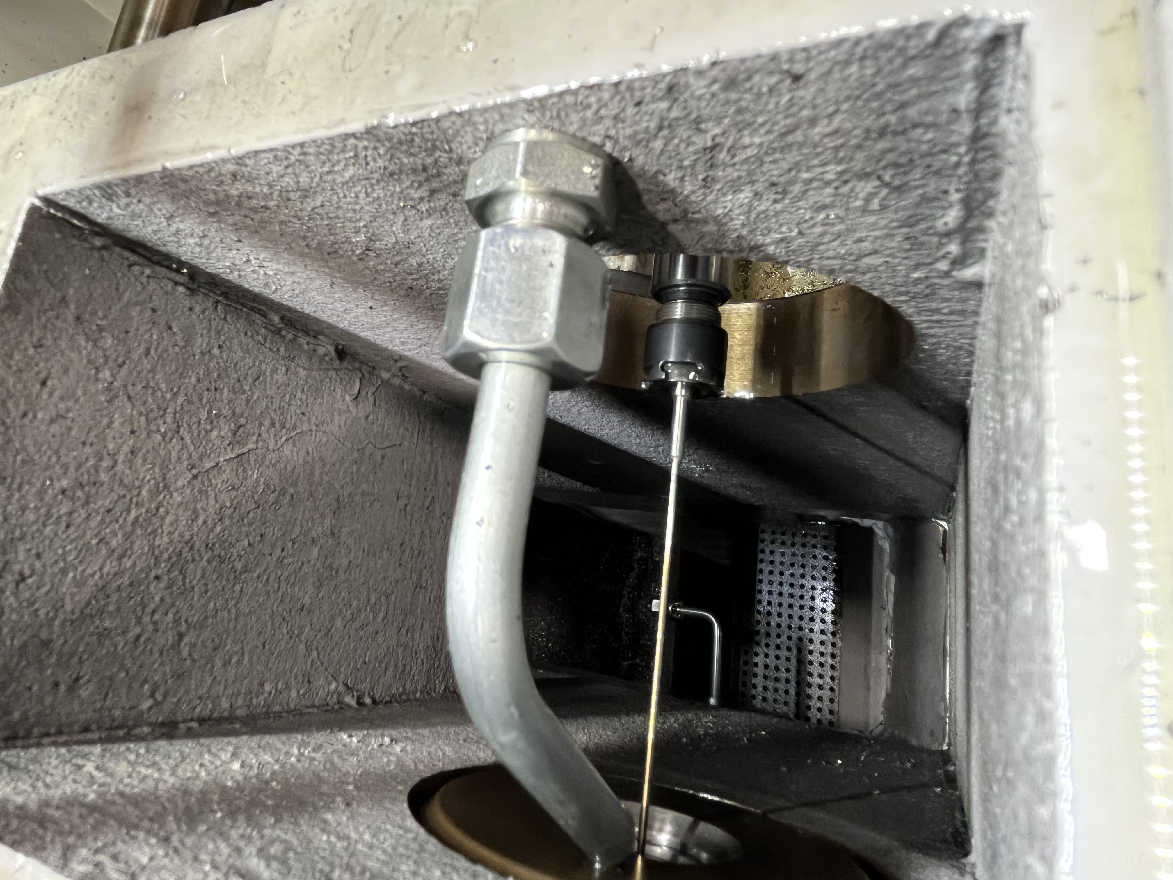
BTA drill head jamming is one of the most difficult problems to recover from in deep hole drilling. The head binds in the bore, the spindle stops under overload, and the head cannot be retracted by normal means. I have dealt with this on holes from 20mm to 150mm diameter, and the recovery approach depends heavily on how badly the head is wedged.
Problem Description
A jam occurs when the drill head becomes mechanically locked inside the bore. The spindle torque spikes to 100% or more of the rated maximum, the machine triggers an overload alarm, and the head refuses to move in either direction. In severe cases, the drill tube twists visibly before the spindle stalls.
The symptoms are unmistakable. Coolant pressure drops suddenly because the flow path is blocked. The feed axis stops moving. The head cannot be retracted even with the feed motor running at maximum torque. I have seen this happen most often in the 30-80mm diameter range on steel and stainless steel parts.
Assessing Severity
Before attempting recovery, I assess how badly the head is jammed. The spindle torque reading at the time of the jam tells me the severity. A jam at 70-80% of rated torque is mild and often clears with hydraulic flushing. A jam at 100% or above is severe and will likely require mechanical extraction.
| Torque at Jam | Severity | Recommended Recovery |
|---|---|---|
| 50-70% | Mild, early stage | Increase coolant flow, retract |
| 70-90% | Moderate | Hydraulic flushing at max pressure |
| 90-100% | Severe | Hydraulic first, then low-feed advance |
| 100%+ stalled | Critical | Manual removal or bore-out |
I also check whether the drill tube is visibly twisted. A twist of more than 5 degrees over the tube length means the torsional load was high enough to permanently deform the tube. The tube should be replaced after the head is removed, even if the jam is cleared.
Root Causes
Chip packing is the primary cause in my experience. The chips accumulate in the annular space between the drill head and the bore wall rather than evacuating through the chip chamber in the drill tube. When enough chips pack together, they form a solid bridge that wedges the head in place.
Several factors contribute to chip packing. Low coolant pressure at the cutting zone (below 20 bar for most BTA applications) fails to propel chips through the tube. Oversized chips that exceed one-third of the tube ID bridge across the bore. Worn inserts produce stringy chips instead of the short, broken chips that evacuate cleanly.
Insert wear is a common contributor that operators overlook. As the inserts wear, the cutting edge geometry changes and the chips become longer and stringier. A head that ran fine with fresh inserts can jam after 20-30 holes because the inserts have worn enough to change the chip shape. I track insert wear and replace them proactively based on hole count.
Other causes I have encountered include collapsed bore walls from excessive cutting force in thin-wall sections, guide bushing misalignment that forces the head into the wall, and thermal expansion of the workpiece closing the bore around the head.
| Root Cause | Frequency | Telltale Sign |
|---|---|---|
| Chip packing | Most common | Gradual torque rise before jam |
| Bore collapse | Rare on solids, common on thin wall | Sudden torque spike |
| Bushing misalignment | Occasional | One-sided wear on head pads |
| Thermal expansion | Rare | Jam occurs late in the cycle |
Recovery Methods
My first attempt at recovery is always hydraulic. I increase coolant pressure to the maximum the pump can deliver, typically 40-80 bar depending on the machine. The high-pressure flow can sometimes flush the packed chips past the head and free it. I run the coolant at maximum for 30-60 seconds while monitoring the pressure gauge. If the pressure drops suddenly, the chips have cleared and the head is free.
If hydraulic flushing fails, I try a low-feed advance. I set the feed rate to 5-10% of the normal cutting feed, typically 2-5 mm/min, and engage the feed while watching the spindle torque. If the torque drops below 50%, the head is cutting through the packed chips. I stop immediately if the torque rises above 80%.
When these approaches do not work, the head must be removed manually. I disconnect the drill tube from the machine spindle and pull it out from the workpiece using a hydraulic puller or come-along. The pulling force can exceed 5 tons on a badly jammed head. I apply penetrating oil to the jam area and wait 10-15 minutes before pulling.
For the worst cases, I have had to bore out the drill head entirely. This means mounting the workpiece on a different machine and boring through the stuck head with a carbide tool. It destroys the head but saves the workpiece.
Post-Recovery Inspection
After recovering a jammed head, I inspect the drill head and bore before running the next part. The head pads should be checked for scoring or galling. Scored pads will cause poor surface finish and can lead to another jam. I replace the head if the pads show any damage.
The drill tube should be checked for straightness. I roll the tube on a flat surface and look for a gap under the center. A bend of more than 0.5mm over the tube length means the tube needs straightening or replacement. A bent tube causes the head to cut off-center and increases the risk of another jam.
I also inspect the bore surface for damage. A jammed head often leaves scoring or gouges in the bore. If the damage is within the bore tolerance, I continue with the same part. If the bore is damaged beyond tolerance, the part is scrapped or sleeved.
I document every jam event in the maintenance log with the root cause and the recovery method used. The log helps identify patterns that point to systemic problems. A machine that jams twice in the same week on different parts likely has a coolant pressure or chip evacuation system issue that needs investigation.
Prevention
Prevention is far more effective than recovery. I use a peck cycle that retracts the head fully every 300-500mm of penetration, depending on the material. Steels require shorter pecks at 300mm. Aluminum can run longer at 500mm.
Spindle torque monitoring catches chip accumulation before it becomes a jam. I set the machine to retract automatically when torque exceeds 70% of the normal cutting range. I track the baseline torque for each job and update it if tool geometry changes.
Coolant pressure at the cutting zone should stay above 20 bar. I check the pressure at the tool tip with a portable gauge during setup. A pressure drop of more than 5 bar from the pump reading indicates a restriction in the coolant supply line.
Key Takeaways
- Chip packing causes most BTA head jams and shows as a gradual torque rise before the jam.
- Try hydraulic flushing at maximum coolant pressure first before mechanical recovery.
- Use a peck cycle of 300-500mm depending on material to prevent chip accumulation.
- Set spindle torque monitoring to retract at 70% of normal cutting torque.
- Manual removal with a hydraulic puller works when hydraulic flushing fails.