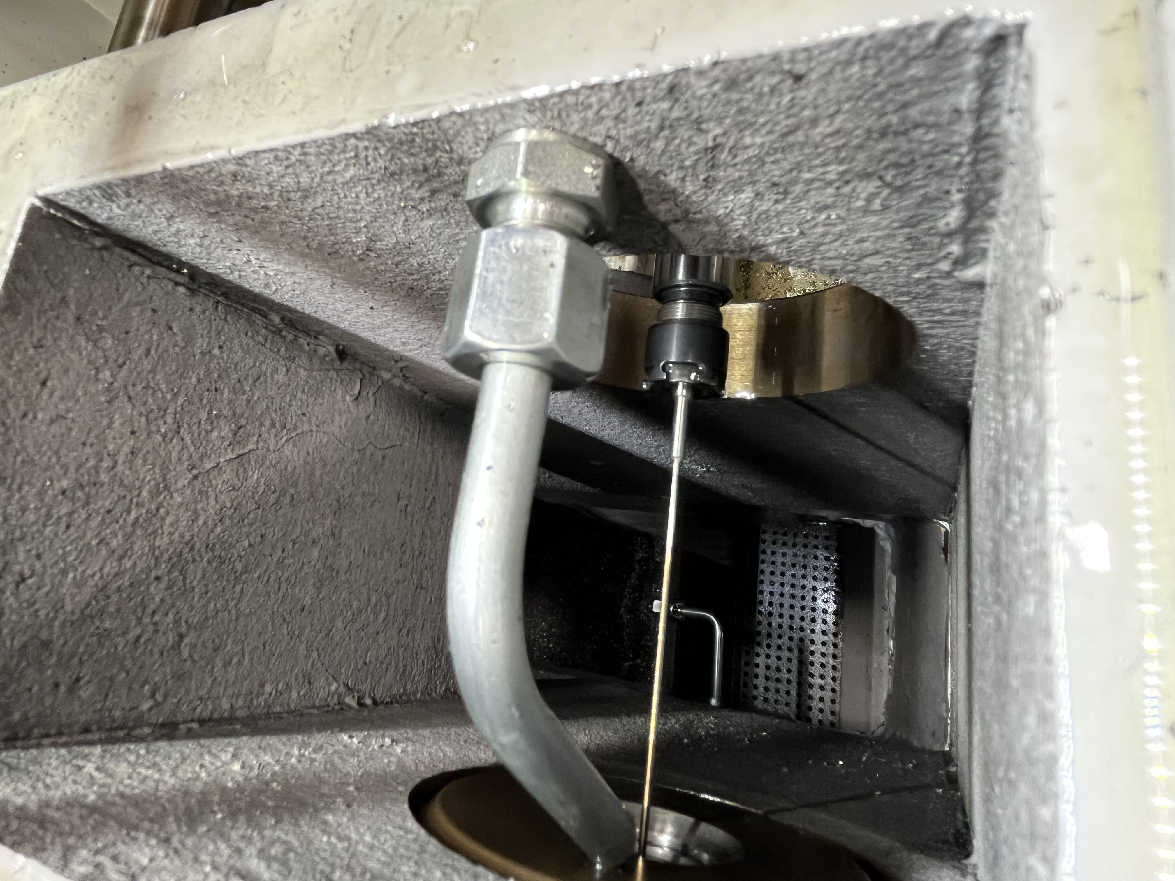
Problem Description
BTA drilling machines face unique wear challenges that standard gun drilling machines don’t. The coolant and chips flow through the center of the drill tube, so internal abrasion is constant. I’ve cut open BTA drill tubes that had worn through 2 mm of wall thickness over 2,000 hours of operation — hidden damage that would eventually cause a catastrophic tube failure.
The support pads on BTA cutting heads also wear in ways that affect bore quality. Worn pads allow the head to chatter, producing a bore with spiral marks that fail surface finish requirements.
Drill Tube Inspection
The drill tube is the most critical component on a BTA machine. Chips traveling at high velocity through the tube bore act like abrasive blasting. I inspect the tube ID with a borescope every 200 operating hours. If I see scoring deeper than 0.5 mm, I replace the tube.
| Inspection Point | Method | Reject Criteria |
|---|---|---|
| Tube ID wear | Borescope | Scoring deeper than 0.5 mm |
| Tube OD at steady rests | Caliper measurement | Wear below nominal by 0.3 mm |
| Flange face | Visual and straightedge | Damage, burrs, or out-of-flat over 0.05 mm |
| Weld joints | Dye penetrant | Any crack indication |
I also check the tube OD at the steady rest contact points. The tube rotates against the steady rest rollers and wears down over time. If the OD is 0.3 mm below nominal, the steady rest loses support and the tube vibrates. Vibration at the head causes oversize bores.
Expanded Maintenance Schedule
I follow this comprehensive maintenance schedule for BTA drilling machines. I developed it by tracking failure patterns across multiple machines over several years:
| Component | Task | Frequency | Estimated Downtime |
|---|---|---|---|
| Drill tube ID | Borescope inspection | Every 200 hours | 15 minutes |
| Drill tube straightness | Roll test on flat surface | Monthly | 10 minutes |
| Drill tube OD at steady rests | Micrometer measurement | Weekly | 5 minutes |
| Drill tube connection threads | Visual + thread gauge inspection | Before every setup | 5 minutes |
| Support pad height | Micrometer measurement | Every 50 operating hours | 10 minutes |
| Support pad wear pattern | Visual inspection | Daily — first part of shift | 2 minutes |
| Rotary union seals | Replace | Every 500 hours | 30-45 minutes |
| Coolant filter | Index or clean | Every 4 hours (steel), every 2 hours (cast iron) | 5 minutes |
| Coolant tank | Clean and replace | Monthly or when fines exceed 100 mg/L | 2-4 hours |
| Coolant concentration | Refractometer test | Weekly | 5 minutes |
| Coolant particle count | Lab analysis | Quarterly | N/A (send-out) |
| Return line elbows | Inspect for erosion wear | Monthly | 10 minutes |
| Replaceable wear pads at elbows | Replace | Quarterly or when worn through | 30 minutes |
| Machine alignment (headstock to guide bush) | Dial indicator | Monthly | 30 minutes |
| Machine alignment (steady rests) | Dial indicator | Quarterly | 45 minutes |
| Steady rest roller condition | Visual + rotation check | Weekly | 5 minutes |
| Slide ways and wipers | Clean and lubricate | Daily | 10 minutes |
| Hydraulic system oil level and filter | Check | Weekly | 10 minutes |
I log every maintenance action on a wall chart so operators can see the history at a glance. If a component fails outside its expected interval, I investigate the root cause before simply replacing the part.
Support Pad Maintenance
Support pads on BTA heads guide the tool along the bore wall. They wear progressively and the cutting head starts to wobble. I measure pad height with a micrometer and replace them when the height drops below the nominal by 0.1 mm.
Pad material matters. For steel, I use carbide pads. For cast iron, I’ve had better luck with PCD-tipped pads that last five times longer. The wrong pad material wears fast and causes bore taper.
I check the pad clearance relative to the cutting head body. If the pad sticks out less than 0.05 mm above the body OD, the head can’t guide properly. If it sticks out more than 0.15 mm, the pad creates excessive friction and the bore surface burns.
Seal Replacement Intervals
BTA machine coolant seals work at high pressure with abrasive fines in the fluid. I replace rotary union seals at 500-hour intervals regardless of visible condition. Waiting until they leak means the seal face is already damaged and may have scored the mating surface.
I use Pop-Off or AutoSense type rotary unions for BTA machines. These designs keep seal faces disengaged when no coolant flows, which extends seal life compared to closed-type seals that run dry between cycles.
Here are the seal replacement intervals I use based on coolant quality:
| Coolant Condition | Rotary Union Seal Life | Recommended Replacement Interval |
|---|---|---|
| Clean coolant, 10-micron filtration | 800-1,200 hours | 500 hours (preventive) |
| Moderate fines, 20-micron filtration | 400-600 hours | 300 hours (preventive) |
| Dirty coolant, no micron rating | 100-200 hours | 100 hours or switch to cleaner filtration |
The single best thing I have done to extend seal life is upgrading to 10-micron coolant filtration. It tripled seal life across all my BTA machines.
Coolant System Maintenance
The BTA return system handles high volumes of chips entrained in the coolant return flow. I clean the chip tank and magnetic separator every shift on heavy production. A clogged return path backs coolant up into the bore, which stops chip flow instantly.
I check the return line for wear at the elbow fittings. Chips hitting the same spot erosion-wear through steel pipe in months. I install replaceable wear pads at all return line elbows and inspect them quarterly.
The coolant return filter needs regular indexing. On my machines, I index the filter drum every 4 hours when running steel. If I let it go 8 hours, pressure differential builds and the pump starves.
Alignment Checks
Machine alignment drifts over time, especially on BTA machines with high thrust loads. I check headstock-to-guide-bushing alignment monthly with a dial indicator. The target is within 0.02 mm TIR.
I also check steady rest alignment quarterly. Each steady rest should be coaxial with the headstock within 0.05 mm. Misaligned steady rests put side load on the drill tube, which causes the tube to wear unevenly and the hole to drift.
The alignment sequence I use:
- Indicate the headstock spindle bore — zero the indicator
- Indicate the guide bushing holder — adjust until within 0.02 mm TIR
- Indicate each steady rest bore — adjust until within 0.05 mm TIR
- Run a test bar through all supports to verify smooth movement
For more on alignment procedures, see machine alignment for deep hole drilling. For coolant system specific maintenance, see coolant system preventive maintenance schedule.
Key Takeaways
- Inspect drill tube ID with borescope every 200 hours — hidden wear causes failures
- Replace support pads when height drops 0.1 mm below nominal
- Clean chip return system every shift — clogs cause bore damage
- Replace rotary union seals at 500-hour intervals, not when they leak
- Keep pad stick-out between 0.05 mm and 0.15 mm above body OD
- Upgrade coolant filtration to 10 micron to triple rotary union seal life
- Follow the comprehensive maintenance schedule — track and log every action
- Check machine alignment monthly — 0.02 mm TIR at headstock to guide bush
- Use Pop-Off or AutoSense rotary unions for BTA machines to prevent dry-running seal damage
- Inspect return line elbows quarterly and replace wear pads as needed
- Log every maintenance action on a wall chart for trend analysis