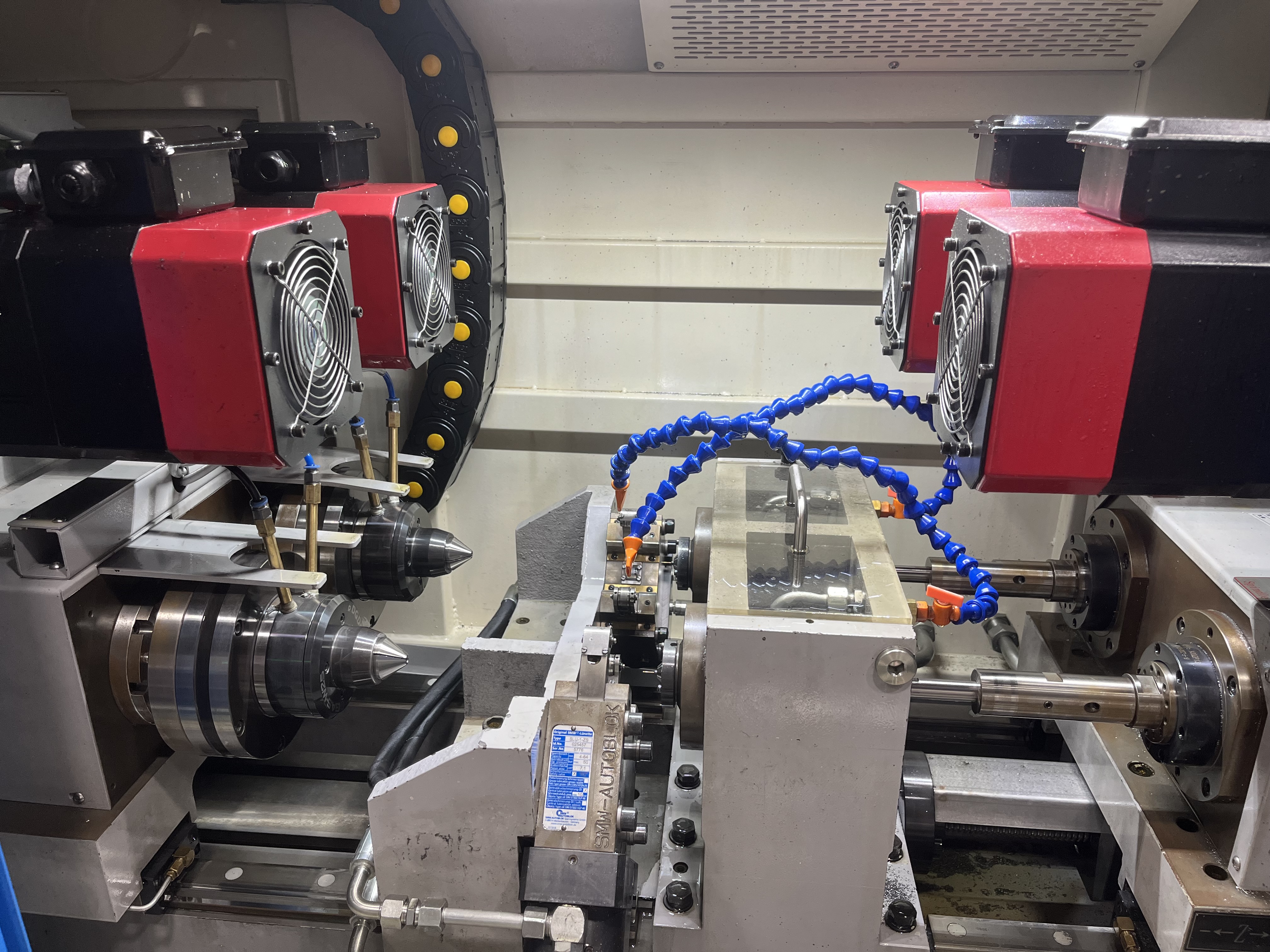
Role of Guide Pads in BTA Drilling
BTA guide pads support the drill head inside the bore and maintain alignment during the cut. They slide against the freshly machined bore wall and provide the bearing surface that keeps the drill head centered. Without properly functioning guide pads, the drill head wanders and the bore drifts off tolerance.
The pads experience continuous sliding contact under high pressure. Coolant pressure in BTA drilling typically runs between 15-40 bar (220-580 psi), and the pads must withstand both the hydrostatic forces and the cutting forces transmitted through the drill head. In my experience, guide pad condition is the single most common cause of BTA bore quality problems.
Normal Wear Patterns
Normal wear is even across the pad surface with a uniform polished appearance. The leading edge of the pad typically shows slightly more wear than the trailing edge. This is normal and results from the pad entering the cut zone first.
I measure pad thickness with a micrometer at three points: the leading edge, the center, and the trailing edge. I compare each measurement to the original pad dimension. Normal wear of 0.02-0.05 mm per job is acceptable for most applications.
| Wear Amount | Action Required |
|---|---|
| 0 - 0.05 mm | Acceptable, continue monitoring |
| 0.05 - 0.10 mm | Plan replacement at next convenient change |
| 0.10 - 0.15 mm | Replace before next job |
| Over 0.15 mm | Replace immediately, risk of tool damage |
The pads should be replaced when wear exceeds 0.10 mm from the original size. At this point, the clearance between the drill head and the bore wall increases enough to allow the drill head to tilt within the bore.
Uneven Wear and What It Indicates
Uneven wear is the most valuable diagnostic indicator in BTA drilling. The wear pattern tells me exactly what is misaligned.
If one pad is worn more than the other, the drill head is tilted in the bore. This usually indicates that the machine spindle is not aligned with the bore axis. I check the machine alignment with a test bar and adjust the headstock.
If the leading edge shows heavy wear while the trailing edge is untouched, the drill head is skewed relative to the feed direction. This can be caused by a bent drill tube or a misaligned support bracket.
If the wear is localized in a band rather than spread across the pad, the bore wall has an irregularity. A hard spot in the material or a previous drill wander mark creates a high spot that contacts only part of the pad.
Wear Life and Material Selection
Carbide guide pads last 3-5 times longer than hardened steel pads. In production applications, I use carbide pads exclusively. The higher upfront cost (about 80-150 USD per pad vs 30-60 USD for steel) is offset by longer life and more consistent bore quality.
| Pad Material | Typical Life (linear meters drilled) | Cost per Pad | Cost per Meter |
|---|---|---|---|
| Hardened steel (HRC 58-62) | 50-100 m | $30-60 | $0.60 |
| Carbide (C2 grade) | 200-400 m | $80-150 | $0.38 |
| Coated carbide (TiAlN) | 300-500 m | $120-200 | $0.40 |
I have found that C2 grade carbide (6% cobalt, 94% tungsten carbide) provides the best balance of wear resistance and toughness for BTA guide pads in steel applications. For aluminum or brass, I use a micro-grain carbide that resists galling.
Factors That Accelerate Wear
Pad wear accelerates significantly at higher feed rates. The higher cutting forces increase the contact pressure between the pads and the bore wall. I have measured pad wear rate doubling when feed rate increases from 0.08 mm/rev to 0.15 mm/rev in 4140 steel.
Coolant concentration affects pad wear. At concentrations below 5% oil-in-water emulsion, the lubricity drops and pad wear increases. I maintain coolant concentration at 8-10% for BTA drilling to ensure adequate pad lubrication.
Contaminated coolant causes abrasive wear on the pads. Chips and fine particles in the coolant act as lapping compound between the pad and the bore wall. I check the coolant filtration system when I see accelerated pad wear.
Replacement Procedure
I always replace pads in sets to maintain consistent clearance. Mixing new and worn pads creates uneven clearance around the drill head. The new pads carry more load and wear prematurely.
Before installing new pads, I clean the pad slots in the drill head thoroughly. Chips or debris under the pad will push the pad out of position and cause uneven wear. I use a feeler gauge to verify that the pad sits flush in the slot.
After installation, I measure the assembled drill head diameter across the pads with a micrometer. The diameter should match the drill head body diameter plus two times the pad thickness. If the diameter is too large, the pads will bind in the bore. If too small, the clearance will cause vibration.
Key Takeaways
- Replace BTA guide pads when wear exceeds 0.10 mm from the original size.
- Uneven pad wear patterns diagnose specific misalignment conditions.
- Carbide pads last 3-5 times longer than steel pads in production applications.
- Always replace pads in sets to maintain consistent clearance.
- Coolant concentration below 5% accelerates pad wear significantly.