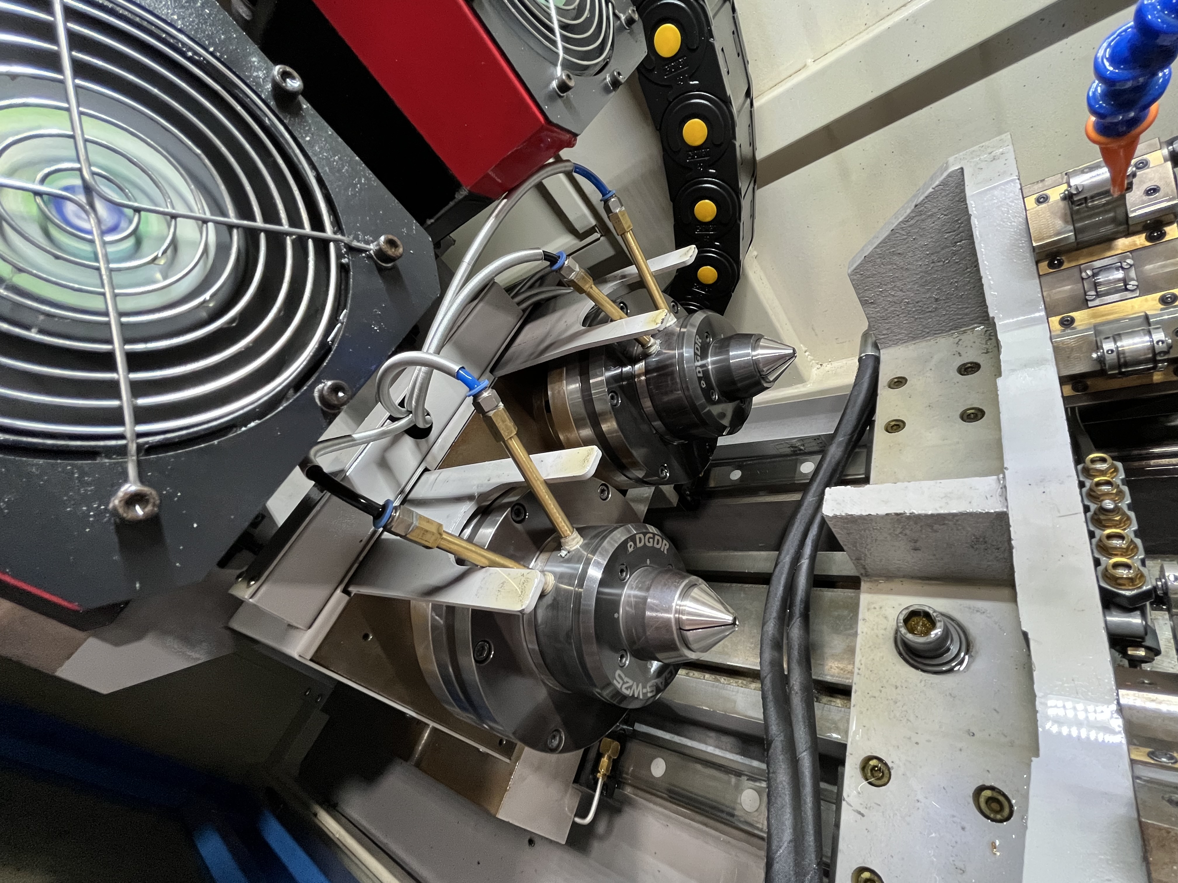
Chip blockage in BTA drilling happens when chips accumulate inside the drill tube and restrict the coolant flow path. I have seen this on holes as small as 18mm diameter and as large as 200mm, and the damage is always expensive. When the tube blocks, coolant pressure spikes, feed drops, and the tool can fail within seconds if not caught in time.
Problem Description
The coolant delivery system in BTA drilling serves two purposes: lubricating the cutting zone and transporting chips through the drill tube back to the chip tank. When the tube blocks, both functions stop. The coolant pressure at the pump rises sharply because the flow path is restricted. The cutting zone loses lubrication, and the chips pack tighter.
I watch for three signs of blockage. The coolant pressure gauge shows a rise of 5-10 bar above the normal operating pressure. The spindle torque fluctuates as chips pack and release. The machine may also show a gradual feed-rate reduction if the CNC is in feed-per-revolution mode, because the spindle load causes the drive to slow down.
If the blockage is not cleared, the packed chips weld to the bore surface under pressure and heat. The drill tube can burst from internal pressure in extreme cases. I have pulled drill tubes that were split open from chip pressure — the tube wall bulges outward at the blockage point.
Root Causes
The most common cause I see is chip size mismatch. The chips produced by the cutting inserts are too large for the tube diameter. In BTA drilling, the chip chamber is the annular space between the tube OD and the bore wall on single-tube systems, or the tube ID itself on double-tube systems. Chips that exceed one-third of the available clearance will bridge across and form a blockage.
| Chip Type | Clearance Needed | Blockage Risk |
|---|---|---|
| Short C-shaped (ideal) | 1/3 of tube ID or less | Low |
| Long stringy | >1/2 of tube ID | High |
| Ribbon chips | Full tube ID | Immediate |
| Broken fine chips | <1/4 of tube ID | Very low |
Insert geometry drives chip size. I use inserts with positive rake angles and molded chip breakers for BTA work. Flat-top inserts without chip breakers produce stringy chips that cause blockages in minutes. The feed rate also matters — running below 0.04 mm/rev on a 30mm head produces thin chips that curl into tight spirals that pack easily.
Coolant flow rate below the recommended level is another contributor. Each BTA head has a minimum coolant flow specified by the manufacturer, typically 80-150 liters per minute per 25mm of head diameter. Running below this rate reduces the chip transport velocity inside the tube and lets chips settle and accumulate.
Chip Formation Control
The chip shape determines whether blockage occurs or not. I evaluate chip formation within the first 20mm of drilling on every new job. The chips should come out of the tube as small, broken segments no larger than one-third of the tube ID.
I classify chips into four categories during the setup run:
| Chip Type | Shape | Blockage Risk | Action Needed |
|---|---|---|---|
| Ideal | Short C-shape, 3-6mm | Low | None |
| Acceptable | Tight spiral, 5-10mm | Moderate | Monitor pressure |
| Marginal | Long stringy, over 10mm | High | Reduce feed or change insert |
| Bad | Ribbon, full tube width | Immediate | Stop and change insert geometry |
Chip shape is controlled by the insert geometry and the feed rate. Inserts with positive rake angles and sharp chip breakers produce short, broken chips. Flat inserts or inserts with negative rake produce stringy chips. I select inserts specifically for their chip-breaking capability, not just for their wear resistance.
Feed rate also affects chip breaking. A feed rate that is too low produces thin chips that curl into tight spirals. A feed rate that is too high produces thick chips that do not break. I adjust feed in 0.005 mm/rev increments to find the sweet spot where chips break cleanly.
Diagnosis
I diagnose the severity of a blockage using the coolant pressure reading. A pressure increase of 2-3 bar above baseline is a partial blockage that can be cleared by retracting. An increase of 5 bar or more is a severe blockage that requires the tube to be removed for cleaning.
I also listen to the chip flow at the chip tank. Normal chip flow produces a steady rattling sound as chips exit the tube. A quiet tank with intermittent chip clusters means the chips are bunching up inside the tube.
When I suspect a blockage, I retract the head and run the coolant at full flow for 10-15 seconds. If the pressure drops back to baseline, the blockage was cleared. If the pressure stays high, the blockage is packed tight and needs manual cleaning.
Solutions
For partial blockages, I retract the head to the starting position and cycle the coolant pressure between high and low for 30 seconds. The pressure cycling helps break up the packed chips and flush them out. I run the coolant at maximum flow, typically 150-200 L/min depending on the machine, and watch for the pressure to drop.
For severe blockages, I remove the drill tube from the machine entirely. I place the tube on a rack and push a cleaning brush through it using a flexible drive shaft. The brush diameter should match the tube ID within 1mm. I run coolant through the tube afterward and catch the chips in a bucket to verify the tube is clear.
I check the tube ID for damage after cleaning. A tube that has been bulged by chip pressure is weakened and should be replaced. I measure the tube OD at the blockage point with a micrometer. Any increase of more than 0.1mm over the original diameter means the tube is permanently damaged.
Prevention
I match the chip size to the tube diameter by selecting inserts with the right chip breaker geometry. For a 30mm BTA head with a 20mm tube ID, the chips should be no larger than 6-7mm in any dimension. I test the chip shape on the first hole of each job and adjust the feed in 0.01 mm/rev increments until I get short C-shaped chips.
Coolant flow rate must stay above the minimum specified by the head manufacturer. I installed a flow meter on each of my BTA machines so I can see the actual flow rate during drilling. If the flow drops below 80% of the target, I check the coolant pump and filter before running the next part.
I also set a pressure alarm on the coolant system. If the pressure rises more than 3 bar above the baseline reading for that job, the machine retracts automatically and cycles the coolant to clear the restriction. This has prevented tool damage on dozens of jobs.
Key Takeaways
- Chip size must be one-third or less of the tube clearance to avoid bridging and blockage.
- Use inserts with molded chip breakers and positive rake angles for BTA drilling.
- Monitor coolant pressure as the primary blockage indicator — a 5-bar rise means immediate retraction.
- Install a flow meter on each BTA machine to verify coolant delivery rate.
- Clean blocked tubes with a properly sized brush and check for permanent tube damage afterward.